Rev. 1.50, 10/04, page 11 of 448
2.2.2 General Registers
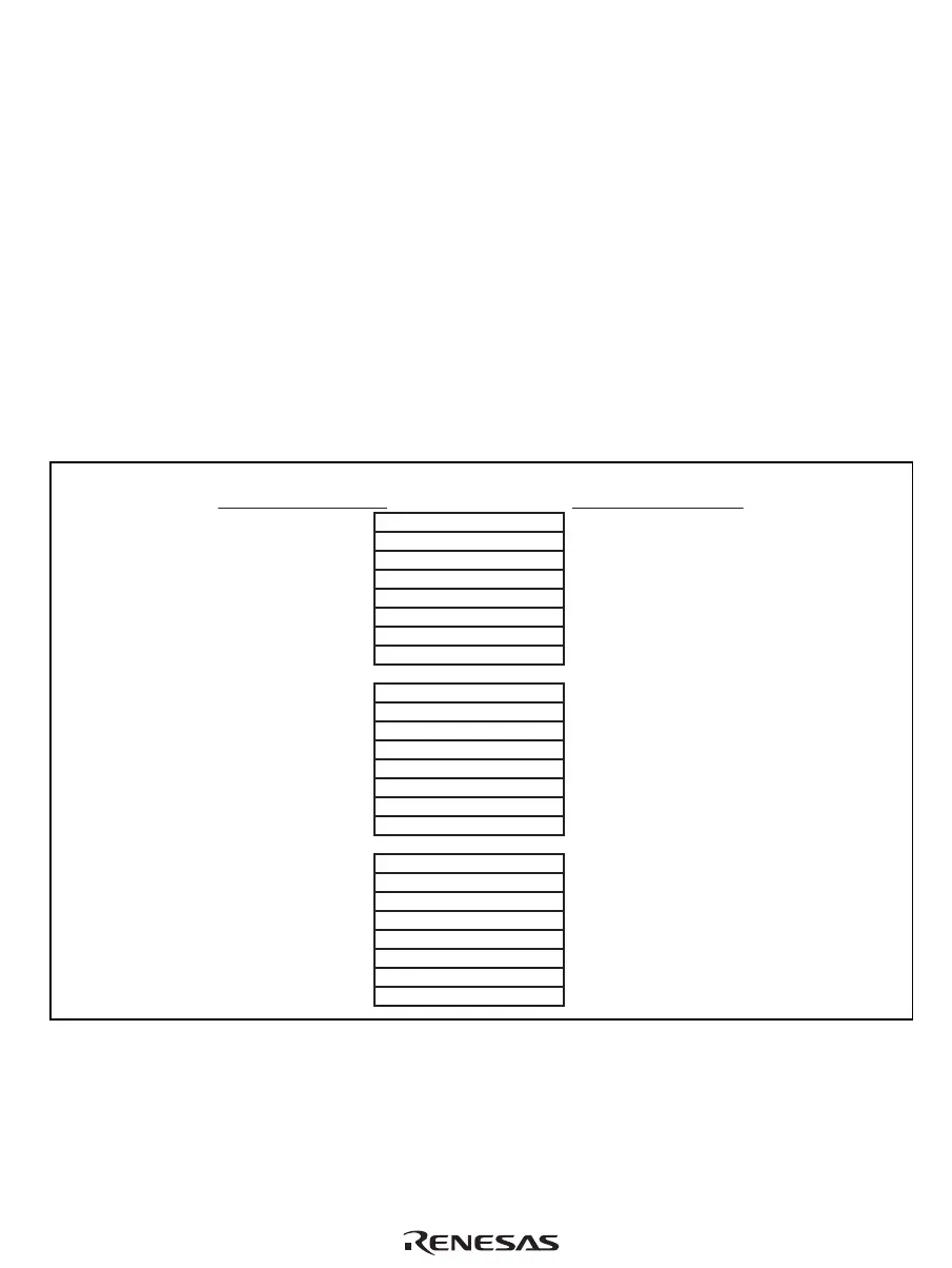
Figure 2.3 shows the relationship between the processing modes and general registers. The SH-4A
has twenty-four 32-bit general registers (R0_BANK0 to R7_BANK0, R0_BANK1 to
R7_BANK1, and R8 to R15). However, only 16 of these can be accessed as general registers R0
to R15 in one processing mode. The SH-4A has two processing modes, user mode and privileged
mode.
• R0_BANK0 to R7_BANK0
Allocated to R0 to R7 in user mode (SR.MD = 0)
Allocated to R0 to R7 when SR.RB = 0 in privileged mode (SR.MD = 1).
• R0_BANK1 to R7_BANK1
Cannot be accessed in user mode.
Allocated to R0 to R7 when SR.RB = 1 in privileged mode.
SR.MD = 0 or
(SR.MD = 1, SR.RB = 0)
R0_BANK0
R1_BANK0
R2_BANK0
R3_BANK0
R4_BANK0
R5_BANK0
R6_BANK0
R7_BANK0
R0
_
BANK0
R1
_
BANK0
R2
_
BANK0
R3
_
BANK0
R4
_
BANK0
R5
_
BANK0
R6
_
BANK0
R7
_
BANK0
R0_BANK1
R1_BANK1
R2_BANK1
R3_BANK1
R4_BANK1
R5_BANK1
R6_BANK1
R7_BANK1
R0
_
BANK1
R1
_
BANK1
R2
_
BANK1
R3
_
BANK1
R4
_
BANK1
R5
_
BANK1
R6
_
BANK1
R7
_
BANK1
R0
R1
R2
R3
R4
R5
R6
R7
R0
R1
R2
R3
R4
R5
R6
R7
R8
R9
R10
R11
R12
R13
R14
R15
R8
R9
R10
R11
R12
R13
R14
R15
R8
R9
R10
R11
R12
R13
R14
R15
(SR.MD = 1, SR.RB = 1)
Figure 2.3 General Registers
Note on Programming: As the user's R0 to R7 are assigned to R0_BANK0 to R7_BANK0, and
after an exception or interrupt R0 to R7 are assigned to R0_BANK1 to
R7_BANK1, it is not necessary for the interrupt handler to save and
restore the user's R0 to R7 (R0_BANK0 to R7_BANK0).

 Loading...


