Rev. 1.50, 10/04, page 44 of 448
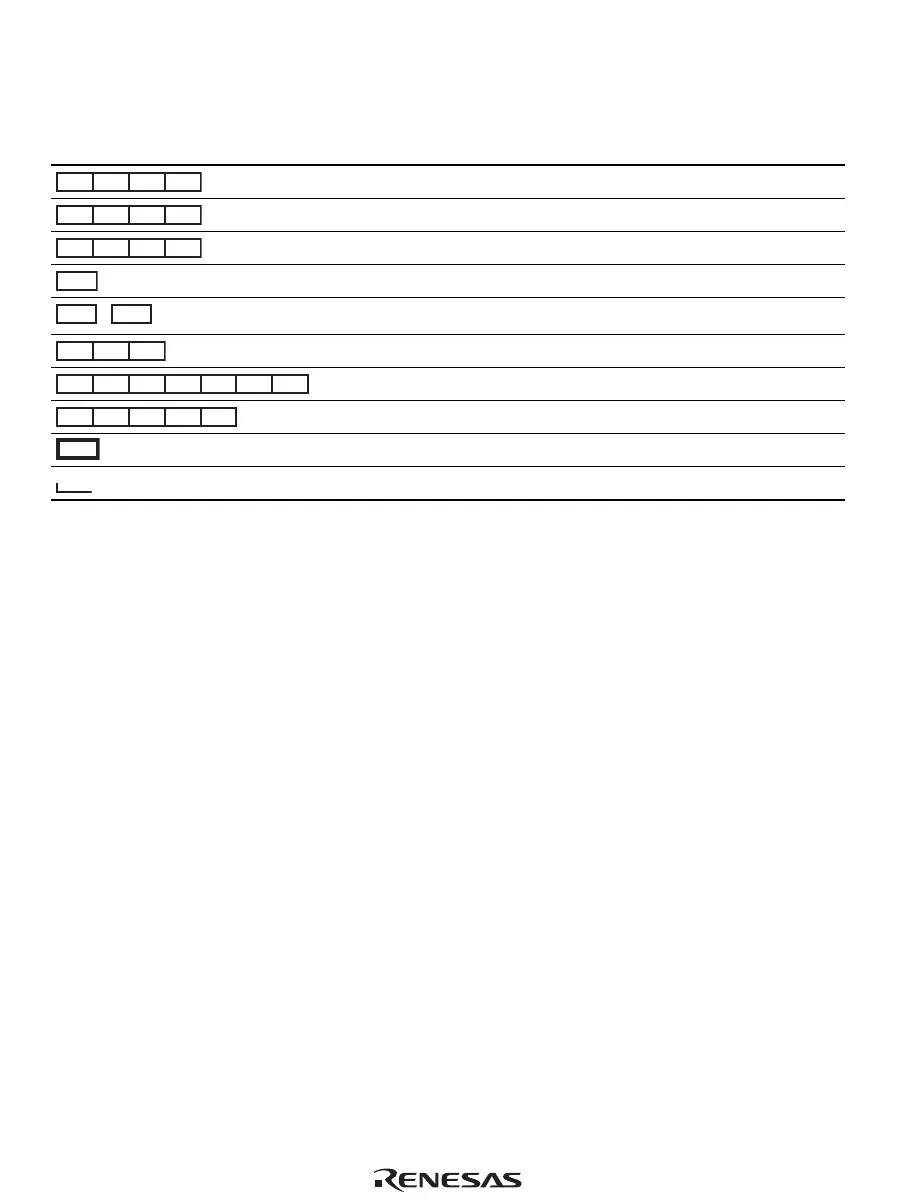
Figure 4.2 shows the instruction execution patterns. Representations in figure 4.2 and their
descriptions are listed in table 4.1.
Table 4.1 Representations of Instruction Execution Patterns
Representation Description
E1 E2 E3 WB
CPU EX pipe is occupied
S1 S2 S3 WB
CPU LS pipe is occupied (with memory access)
s1 s2 s3 WB
CPU LS pipe is occupied (without memory access)
E1/S1
Either CPU EX pipe or CPU LS pipe is occupied
E1S1 E1s1
,
Both CPU EX pipe and CPU LS pipe are occupied
M2 M3 MS
CPU MULT operation unit is occupied
FE1 FE2 FE3 FE4 FE5 FE6 FS
FPU-EX pipe is occupied
FS1 FS2 FS3 FS4 FS
FPU-LS pipe is occupied
ID
ID stage is locked
Both CPU and FPU pipes are occupied

 Loading...


