Rev. 1.50, 10/04, page 49 of 448
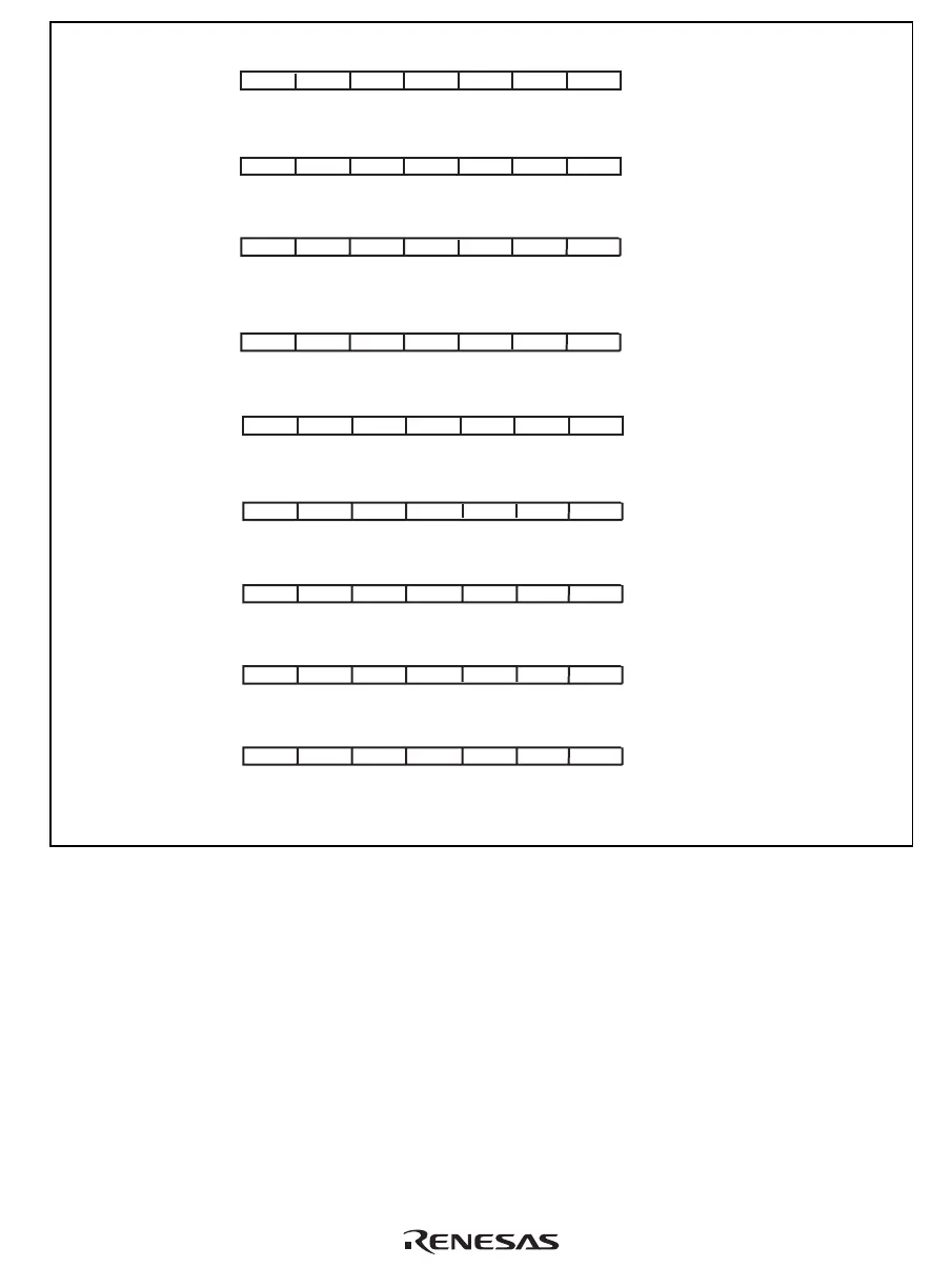
(4-9) STC from DBR/GBR/Rp_BANK/SSR/SPC/VBR/SGR: 1 issue cycle
I1 I2 ID s1 s2 s3
WB
(4-10) STC from SR: 1 issue cycle
(4-11) STC.L from DBR/GBR/Rp_BANK/SSR/SPC/VBR/SGR: 1 issue cycle
I1 I2 ID
WB
I1 I2 ID S1 S2 S3
E1s1 E2s2 E3s3
WB
(4-12) STC.L from SR: 1 issue cycle
(4-13) LDS to PR: 1 issue cycle
I1 I2 ID
WB
I1 I2 ID S1 S2 S3
E1S1 E2S2 E3S3
WB
I1 I2 ID s1 s2 s3
WB
(4-14) LDS.L to PR: 1 issue cycle
I1 I2 ID s1 s2 s3
WB
(4-15) STS from PR: 1 issue cycle
I1 I2 ID S1 S2 S3
WB
(4-16) STS.L from PR: 1 issue cycle
(I1) (I2) (ID) (??1) (??2) (??3)
(WB)
(4-17) BSRF, BSR, JSR delay slot instructions (PR set): 0 issue cycle
The value of PR is changed in the E3 stage of delay slot instruction.
When the STS and STS.L instructions from PR are used as delay slot instructions,
changed PR value is used.
Notes:
Figure 4.2 Instruction Execution Patterns (5)

 Loading...


