Rev. 1.50, 10/04, page 21 of 448
Address A
A
70707070
31
15 0 15 0
31 0
15 0
31 0
23 15 7 0
A + 1 A + 2 A + 3
Byte 0
Word 0
Longword
Word 1
Byte 1 Byte 2
Byte 3
A + 11
70707070
31
15 0
23 15 7 0
A + 10 A + 9 A + 8
Byte 3
Word 1
Longword
Word 0
Byte 2 Byte 1 Byte 0
Address A + 4
Address A + 8
Address A + 8
Address A + 4
Address A
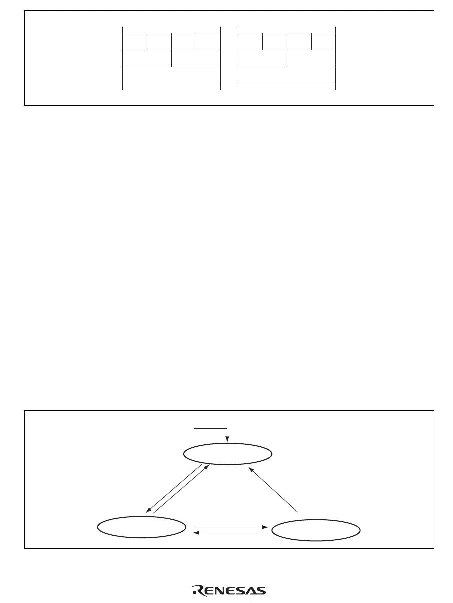
Big endian Little endian
Figure 2.7 Data Formats in Memory
For the 64-bit data format, see figure 2.5.
2.6 Processing States
This LSI has major three processing states: the reset state, instruction execution state, and power-
down state.
Reset State: In this state the CPU is reset. The reset state is divided into the power-on reset state
and the manual reset.
In the power-on reset state, the internal state of the CPU and the on-chip peripheral module
registers are initialized. In the manual reset state, the internal state of the CPU and some registers
of on-chip peripheral modules are initialized. For details, see register descriptions for each section.
Instruction Execution State: In this state, the CPU executes program instructions in sequence.
The Instruction execution state has the normal program execution state and the exception handling
state.
Power-Down State: In a power-down state, CPU halts operation and power consumption is
reduced. The power-down state is entered by executing a SLEEP instruction. There are two modes
in the power-down state: sleep mode and standby mode.
From any state
when reset/manual
reset input
Reset state
Instruction execution state
Sleep instruction execution
Power-down state
Interrupt occurence
Reset/manual
reset clearance
Reset/manual
reset input
Reset/manual
reset input
Figure 2.8 Processing State Transitions

 Loading...


