RFL 9300 transmit addresses are user selectable from “0016” to “4079” and are set to different values at the
local and remote units. The sum of the local and remote addresses must equal 4095. For example, if the local
address is set to “4000” then the remote address must be set to “0095”. The address programmed at the local
unit is transmitted to the remote unit for address verification. If the correct address is not verified, an address
alarm will be displayed on the 9300 front panel.
When addressing is not required, the user can disable the addressing feature of the RFL 9300 by setting the
transmit addresses of both the local and remote 9300s to “0000”. For more information, refer to the start-up
procedure at the beginning of this section.
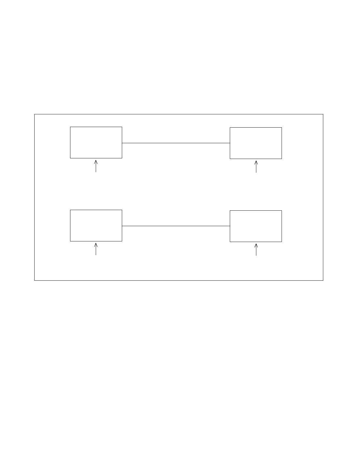
TRANSMIT ADDRESS
SET TO “0000”
TRANSMIT ADDRESS
SET TO “0000”
LOCAL
9300
REMOTE
9300
TRANSMIT ADDRESS
SET TO “0000”
LOCAL
9300
REMOTE
9300
DEDICATED LEASED TELEPHONE LINE
DIRECT FIBER OPTIC CABLES
TRANSMIT ADDRESS
SET TO “0000”
Figure 6-31. A typical two-terminal installation where addressing is not required
6.6.2 THREE-TERMINAL ADDRESSING
Three-terminal addressing is similar in principle to two-terminal addressing as described in para. 6.6.1 with the
exception that the units are installed in sets of three, where one unit is installed at each leg of a protected
power line. One of the units is arbitrarily referred to as the local unit and the other two are referred to as re-
mote 1 and remote 2. Figure 6-32 shows a typical installation using three-terminal addressing. Note that two
transmit addresses (TX1 and TX2) must be programmed at each terminal. This means that a total of six
transmit addresses must be programmed for a three-terminal installation. There are a few simple rules that
must be followed when addressing a three-terminal installation:
1. Addresses under 0016 are not allowed.
2. The TX1 and TX2 addresses must be different at each site.
3. The TX1 address of a given site and the TX1 address of its “mate” must add up to 4095.
For step-by-step three-terminal addressing instructions, refer to para. 6.3.2.
RFL 9300 RFL Electronics Inc.
January 30, 2002 6-62 (973) 334-3100