SECTION 26: EXPANSION CHASSIS
LOW VOLTAGE BATT VOLTAGE
1
2 3 4 5
!
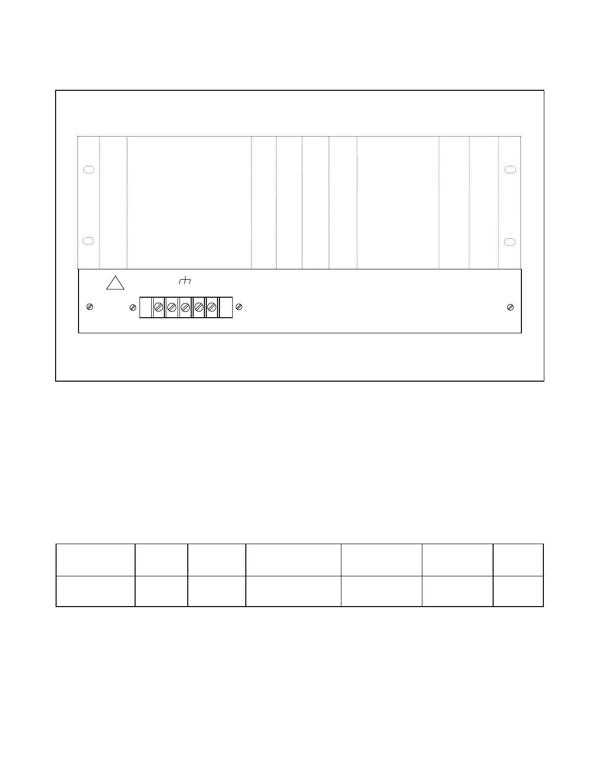
TB12
Figure 26-1. Typical RFL 9300 Expansion Chassis, rear view
The rear view of the RFL 9300 expansion chassis is shown in Figure 26-1. The front view of the expansion
chassis is not shown since it is a blank panel. The expansion chassis allows the RFL 9300 to operate from
250VDC station battery power. The expansion chassis contains a power supply which converts 250VDC station
battery power to 48VDC. The 48VDC is then used to power the RFL 9300 chassis via TB1 at the rear of the Re-
lay I/O module (Section 20). The expansion chassis is an option which is only used in some RFL 9300 installa-
tions. Table 26-1 provides general information about the expansion chassis, Table 26-2 is a list of replaceable
parts, Figure 26-2 is a component locator drawing, and Figure 26-3 is a schematic diagram.
Table 26-1. Expansion Chassis, General Information
Model Number Width Height Expansion Chassis
Assembly Number
Power Supply
Assembly Number
Input Voltage
Range
Maximum
Input
Current *
POWER CONV
I/O - 250VDC
17.19 in
(43.66 mm)
1.718 in
(4.36 mm)
105875 106350 210 to 280 VDC 305ma
* Maximum current is drawn when power supply module is operating at full load with minimum voltage present at its input terminals.
RFL 9300 RFL Electronics Inc.
February 7, 2000 26 - 1 (973) 334-3100