SECTION 23: G.703 INTERFACE I/O MODULE
93 G.703
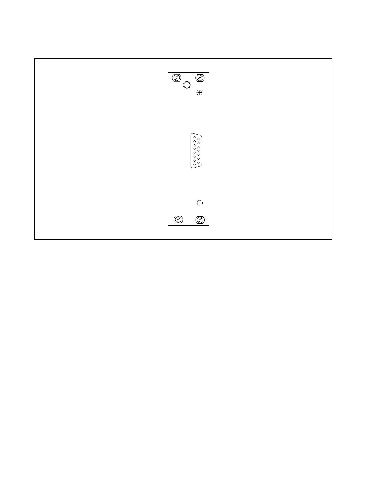
Figure 23-1. RFL 93 G.703 Interface I/O Module
23.1 DESCRIPTION
The RFL 93 G.703 Interface I/O Module (Fig. 23-1), plugs into the back of the 9300 chassis and provides a full
duplex serial link to a remote 93 G.703 module. It does this without an additional board plugged into the front of
the chassis since all logic is contained in the rear module.
23.2 CONTROLS AND INDICATORS
The RFL 93 G.703 Interface I/O Module circuit board contains three programmable jumpers that prepare it for
use, two potentiometers, three test points and a rear-panel 15-pin D-subminiature connector. Figure 23-2 shows
the jumper locations, and their functions are described below. The jumpers, potentiometers, and test points can
only be accessed when the RFL 93 G.703 is out of the chassis or is on a card extender.
RFL 9300 RFL Electronics Inc.
February 7, 2000 23 - 1 (973) 334-3100