CURRENT
TRANSFORMER
ANALOG
SWITCH
SENSE
AMPLIFIER
CURRENT-
TO-VOLTAGE
CONVERTER
HIGH-
CURRENT
BUFFER
FULL-WAVE
RECTIFIER
200-HZ
LOW-PASS
FILTER
AND
BUFFER
OUTPUT TO
PHASE
CONTROLLER
MODULE
AND OSCILL-
OGRAPHY
BOARD
INPUT CURRENT
FROM CT ON
PROTECTED
LINE
TEST
WINDING
POWER UP RESET
FROM PHASE
CONTROLLER
MODULE
DC RESTORE
FROM PHASE
CONTROLLER
MODULE
SENSE
WINDING
FEEDBACK
WINDING
HIGH-CURRENT
BUFFER
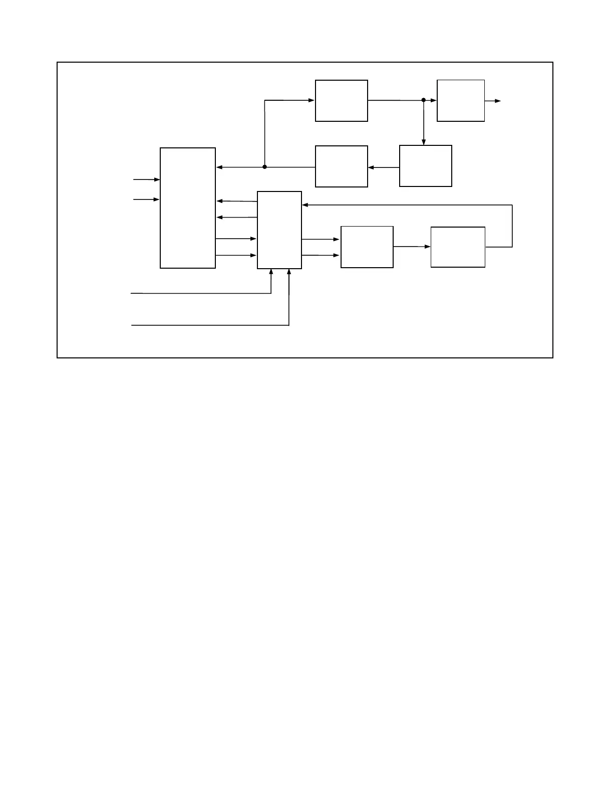
Figure 11-3. Block diagram, RFL 93B ACT I/O Auxiliary Current Transformer I/O Module
Current transformer T1 has one primary winding which is a single-turn winding for normal operating currents.
When current is applied to the T1 primary, sense amplifier U1 senses the signal developed on the 1000-turn
secondary winding. U1 inverts this signal and converts it to a current used to drive T1's 4000-turn feedback
winding. This current is fed to the feedback winding through three sections of analog switch U4. The current in
the feedback winding reduces the signal on the sense winding to near zero, canceling the flux in the transformer
core. The current needed in the feedback winding is equal to the primary current multiplied by the pri-
mary/feedback winding turns ratio.
The current in the feedback winding is fed to operational amplifier U2, which serves as a current-to-voltage con-
verter. U2's output is fed to a high-current buffer formed from transistors Q5 through Q8 and their associated
components. The scaling factors for the current-to-voltage converter are determined by resistors R17 and R18.
R18 is a factory-selected part; its value is selected to compensates for low-pass filter losses and errors in the
4000-turn transformer winding. The output of the current-to-voltage converter is limited to 10.3 volts by the full-
wave rectifier formed from diodes CR17 through CR20 and Zener diode CR21. The limiting function only limits
the output voltage; the circuit will cancel flux and prevent saturation of T1's core for input currents as large as
250 A
rms
.
The final output stage of the RFL 93B ACT I/O is a three-pole, 200-Hz, low-pass filter formed from resistors R21
through R23 and capacitors C7 through C9. The output of this filter is buffered by operational amplifier U3. This
filter provides anti-aliasing for the A/D converter on the phase controller module (Section 12.)
The Phase Controller also has some additional control over the RFL 93B ACT I/O, in terms of power-up and
power system disturbances with a dc component. Two logic-level signals from the RFL 93B PC control analog
switch U4: POWER UP RESET (edge connector terminal P1-C2) and DC RESTORE (P1-A2). During system
initialization, POWER UP RESET is held high, keeping the output of the sense amplifier disconnected from T1's
feedback winding. This is done for 650 ms, and provides a smooth power-up sequence for the RFL 93B ACT
I/O.
RFL 9300 RFL Electronics Inc.
March 26, 1999 11 - 3 (973) 334-3100