Once the single-pole logic has been initialized, it will begin transmitting a 16-bit status word (Fig.24-5) to the
Supervisor at 264ms intervals. The transmission will be asynchronous with a start bit (active low), 16 data bits
and one stop bit (active high) The message bits will be synchronized to the system clock and will be in the mark,
or logic 1 condition when no messages are being transmitted. SV_DAT (JP1-23) will be utilized to transmit the
message. The first time that the Supervisor detects one of these messages and determines that it is valid, a
message will be sent to the Display Controller rescinding the Single-Pole Chassis alarm. On receiving this mes-
sage the Display Controller will cease sending the initialization message to the single-pole logic.
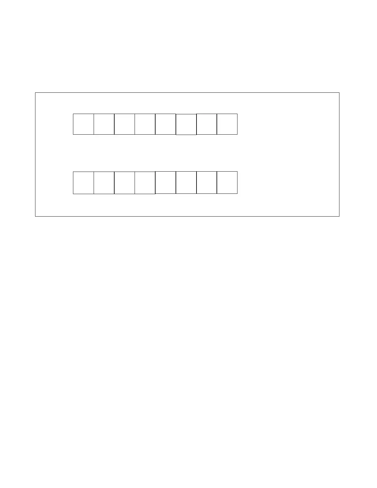
Current Sense Targets Trip Release Code
0 1 2 3 4 5 6 7
CS CS CS CS CS CS TR TR
A1 A2 B1 B2 C1 C2 Bit 0 Bit 1
MSB bits 7-15
Marker Bit DC Current Sense Alarms
0 1 2 3 4 5 6 7
1 0 0 0 0 A B C
LSB bits 0 - 7
Figure 24-5. 16-bit Status messages transmitted by the Single-Pole logic to the Supervisor at 250ms intervals
• Marker Bit Bit 0 - Always a logic 1
• Spare Bits Bits 1- 4
• DC Current Sense Alarm Bits Bits 5 - 7 (Phase [x])
1 = Phase (x) Alarm Active
0 = Phase (x) Alarm not active
• Target Bits Bits 8 - 13 (Phase [x] DC Current Sense - active)
1 = Target On
0 = Target Off
• Trip Release Code Bits 14-15 (active)
24.4.2 NORMAL OPERATION AFTER INITIALIZATION IS COMPLETE
After initialization, the single-pole logic will continue to transmit its 16-bit status message (Fig.24-5) to the Su-
pervisor at 264ms intervals. The Supervisor will not accept any status changes as valid until it receives two
identical messages in succession. If a status change is accepted as valid, the Supervisor will transmit byte 2 of
the status message (Fig.24-5) as received from the single-pole logic to the Display Controller. As long as there
are no changes in single-pole logic status detected by the Supervisor, byte 2 of every 10th status message
(2.64 second interval) will be transmitted to the Display Controller. This is to insure that the Display Controller
will not miss a change in single-pole logic status.
When the Display Controller receives this message it will be saved in NV RAM. If the trip release code received
from the Supervisor differs from the latest code known to the Display Controller, or if a new trip release code is
programmed by the operator, the initialization message (Fig. 24-4) will be transmitted to the single-pole logic,
with bit 7 = logic 1. This will signal the single-pole logic to ignore the target & mode bits but to accept the Trip
Release code.
If the Supervisor has gone 600ms without receiving a status message from the single-pole logic, or if it detects
that the single-pole jumper position on the Supervisor card (J5) has changed, it will declare a SINGLE-POLE
CHASSIS ALARM locally and transmit the alarm message to the Display Controller. As long as this alarm re-
mains active the Display Controller will transmit the initialization message with bit 7 = logic 0, at 750ms intervals.
RFL 9300 RFL Electronics Inc.
August 25, 2000 24 - 9 (973) 334-3100