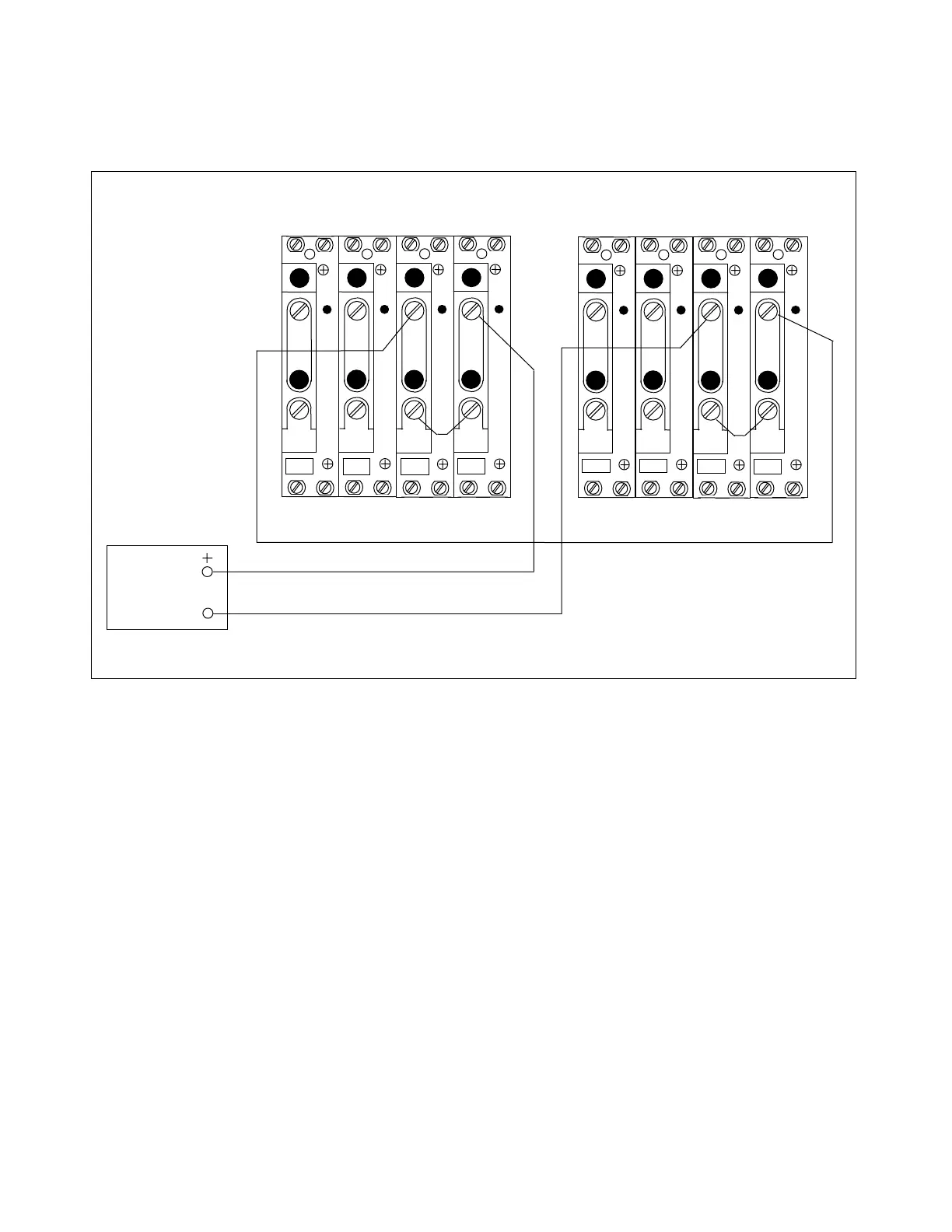
7.4.6 INTERNAL A-B FAULTS
1. Connect the equipment as shown in Figure 7-8.
AC
CURRENT
SOURCE
TB4
TB5
A
C
T
A
C
T
TB6
TB7
A
C
T
A
C
T
3I
0
I
C
I
B
I
A
1 1 1 1
2 2 2 2
TB4
TB5
A
C
T
A
C
T
TB6
TB7
A
C
T
A
C
T
3I
0
I
C
I
B
I
A
1 1 1 1
2 2 2 2
LEFT TERMINAL RIGHT TERMINAL
Figure 7-8. Test connections simulating an internal A-B fault
2. Starting from zero amperes, gradually increase the test current.
At 1.5 amperes, the display will read "ALARM 34 32 31 61 62." This means an LCCT and
general phase controller alarm condition exists on Phase A and Phase B.
Note: All alarms may not be visible on the display controller. Four alarm codes can be
displayed at one time. A partial list is considered normal for this test.
3. Apply 1.5 amperes suddenly.
All red FD indicators on the 93B PC module will flash momentarily, and the A and B trip
indicators on the 93B DISPLAY module will light.
4. Apply a test current of 6 amperes or more.
The red FD indicators on the 93B PC modules monitoring Phase A and Phase B will
light.
5 (optional).
Measure trip times for various current levels.
The results should be roughly the same as for A-G faults.
RFL 9300 RFL Electronics Inc.
October 20, 2004 7 - 15 (973) 334-3100