RFL 9300 RFL Electronics Inc.
October 20, 2004 8 - 20 (973) 334-3100
8.3.3 FIBER OPTIC COMMUNICATIONS
The following procedure verifies end-to-end communications for RFL 9300 relays equipped with fiber-optic mod-
ules. A photometer (Photodyne XE Series or equivalent) will be required to perform this procedure.
1. Make sure the external fibers have been properly connected to the RFL 9300.
The transmit fiber should be connected to the TX bulkhead connector on the 93
FT/FR I/O module at the rear of the RFL 9300. The receive fiber should be connected
to the RX bulkhead connector on the 93 FT/FR I/O module.
2. Disconnect the receive fiber from the 93 FT/FR I/O module, and use a photometer to measure
the incoming power level.
The photometer reading should be within the ranges indicated in Table 8-3.
If the measured average power is less than that shown in the Receiver Sensitivity
column (lower limit with 3-dB margin), there is not enough margin for proper opera-
tion. This could be caused by excessive splicing losses in the fibers, excessive cou-
pling losses, or a line length that exceeds the limits shown in Table 8-3.
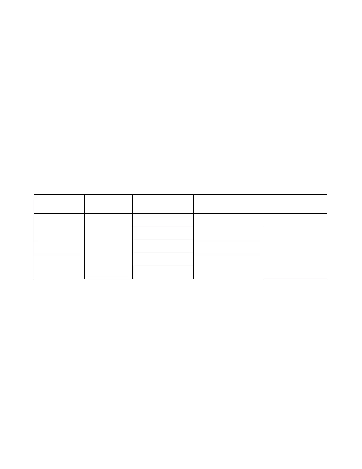
Table 8-3. Acceptable received fiber optic power levels, RFL 9300 Charge Comparison System
Wavelength
And
Emitter Type
Mode Receiver Sensitivity
(Lower Limit)
Receiver Sensitivity
(Lower Limit With
3-dB Margin)
Typical Line Length
850 nm LED Multimode -50 dBm -47 dBm 5 mi (8 km)
1300 nm LED Multimode -40 dBm -37 dBm 11 mi (18 km)
1300 nm LED Singlemode -40 dBm -37 dBm 18 mi (29 km)
1300 nm Laser Singlemode -40 dBm -37 dBm 36.5 mi (59 km)
1550 nm Laser Singlemode -40 dBm -37 dBm 63 mi (102 km)
3. Using the RFL 9300's READ display mode, check the channel delay time by watching the ping-
pong value displayed on the bottom line of the display.
The ping-pong value should be 4.0 or 4.5 ms.
4. Place the RFL 9300 back in the STANDBY display mode.
The display will return to the moving dot pattern.
Fiber optic communications have now been verified. Go on to the next procedure.