SP101
DS101
DS102
DS103
DS104
TP104
TP105
TP101
J105
A
B
J104
NORM
TEST
J103
OUT
IN
TP103
TP102
J102
OUT
IN
OUT
J101
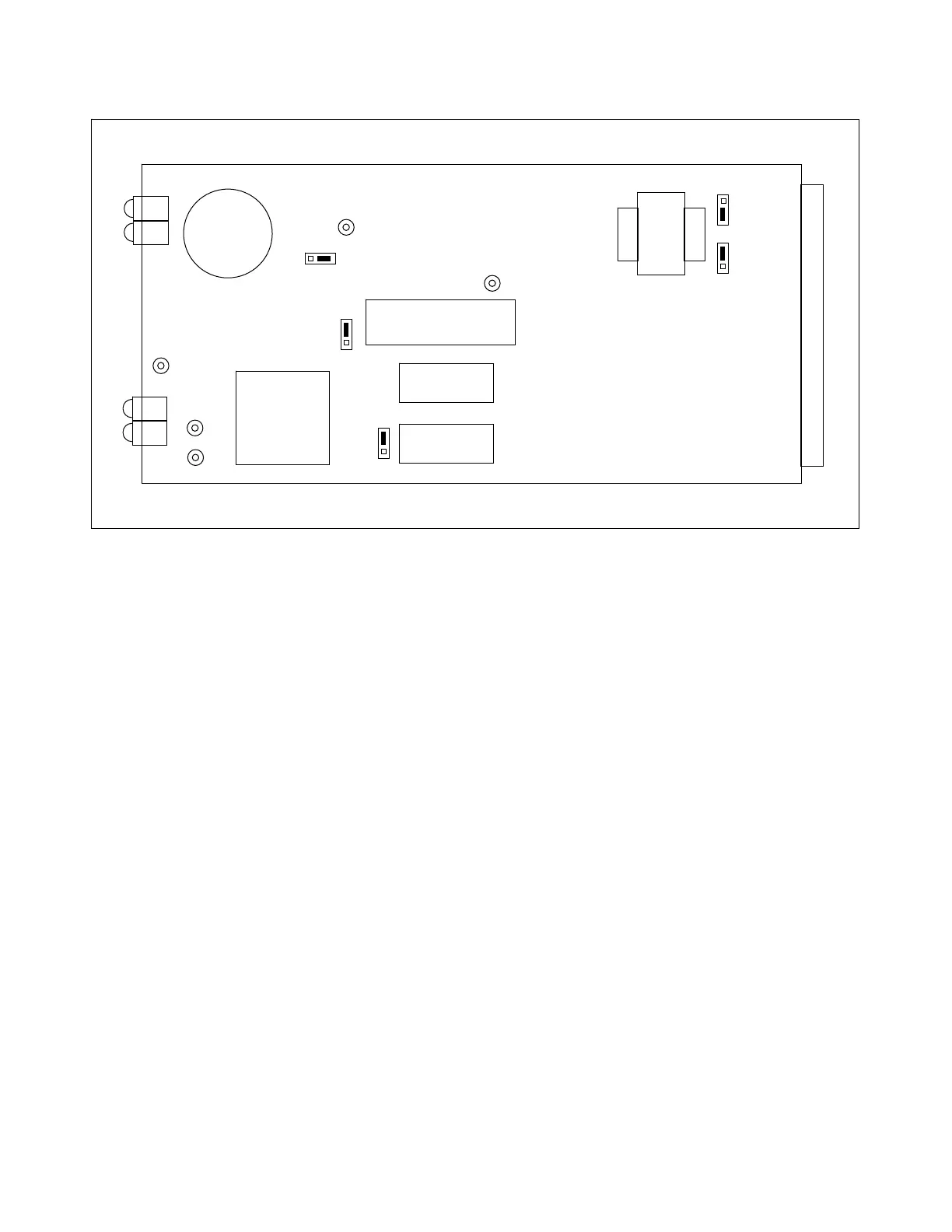
Figure 9-3. Controls and indicators for oscillography board, used in RFL 93B DISPLAY module
LED INDICATORS
DS101 TRIP 1 - Front-panel indicator; lights when the TRIP 1 relay contacts are carrying trip cur-
rents of at least 0.2 amperes. This indicator is latched in non-volatile memory, and can only
be reset by pressing RESET switch SW302 on the display controller board.
DS102 TRIP 2 - Front-panel indicator; lights when the TRIP 2 relay contacts are carrying trip cur-
rents of at least 0.2 amperes. This indicator is latched in non-volatile memory, and can only
be reset by pressing RESET switch SW302 on the display controller board.
DS103 LOR 1 - Front-panel indicator; lights when the LOR 1 dc trip circuit carries currents of at
least 0.2 amperes. This indicator is latched in non-volatile memory, and can only be reset
by pressing RESET switch SW302 on the display controller board.
DS104 LOR 2 - Front-panel indicator; lights when the LOR 2 dc trip circuit carries currents of at
least 0.2 amperes. This indicator is latched in non-volatile memory, and can only be reset
by pressing RESET switch SW302 on the display controller board.
TEST TURRETS
TP101 Ground reference
TP102 IRIG-B test point
TP103 IRIG-B test point
TP104 ACTEL probe test point
TP105 ACTEL probe test point
RFL 9300 RFL Electronics Inc.
August 9, 2001 9 - 7 (973) 334-3100