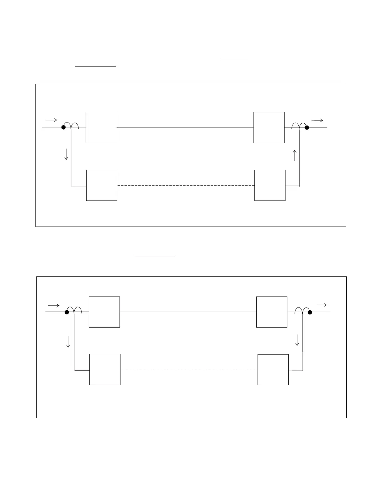
8.4.4.5.1 Two Terminal Systems
If the terminals are wired correctly, then the current going into the local relay
will be the same as the current go-
ing out of the remote 1 relay
, and the differential current on Phase A will be zero. This can be seen in Figure 8-
6.
RFL 9300 RFL Electronics Inc.
October 20, 2004 8 - 31 (973) 334-3100
Station A
Station B
RFL 9300
Two
Terminal
RFL 9300
Two
Terminal
Communications Channel
Local Remote
2 Am
1
s
2 Amps
Figure 8-6. Correctly wired two-terminal system
If there is a phase inversion at the remote 1 relay, the resulting differential current indicated at both stations will
be approximately double the current, or about four amps. This can be seen in Figure 8-7.
Station A
Station B
2 Am
s
2 Amps
RFL 9300
Two
Terminal
RFL 9300
Two
Terminal
Communications Channel
Local Remote
Phase input to
remote 1 relay
inverted
1
Figure 8-7. Phase inversion at remote 1 relay