U24
U16
U17
U27
U30
U23
U28
RZ5
RZ7
U9
C36
+
U25
Y1
P1
U4
U5
U11
U1
U10
U2
U15
U14
U6
U7 U29
DS2
DS1
R18
J5H
J5G
C6
TP4
TP3
TP1
J4
U13
U12
U19U18
U26
R12
R6
R9
R10
R3
R11
R5
R4
R7
R2
R1
R8
R15
R14
R17
R13
R16
C35
C10
C15
C11
C7
C9
C12
C3
C4
C2
C1
C14
C13
C5
C26
C27
C28
C24
C25
C20
C23
C30
C19
C18
C17
C29
C16
TP2
C31
C32
RZ4
RZ2
RZ3
RZ6
RZ9
U3
C34
C37
C38
C33
RZ8
RZ1
U20
J3E
J1A
J2D
J1B
J2C
J3F
ECB 93B SUPERVISOR CONTROL NO. 106303-1 REV A2000 RFL ELECTRONICS, BOONTON, NJ USA
K
J
20
10
1
32
AC
AC
1
J2
J1
J3
J5
DS 1
DS 2
J4
TP 1
TP 2
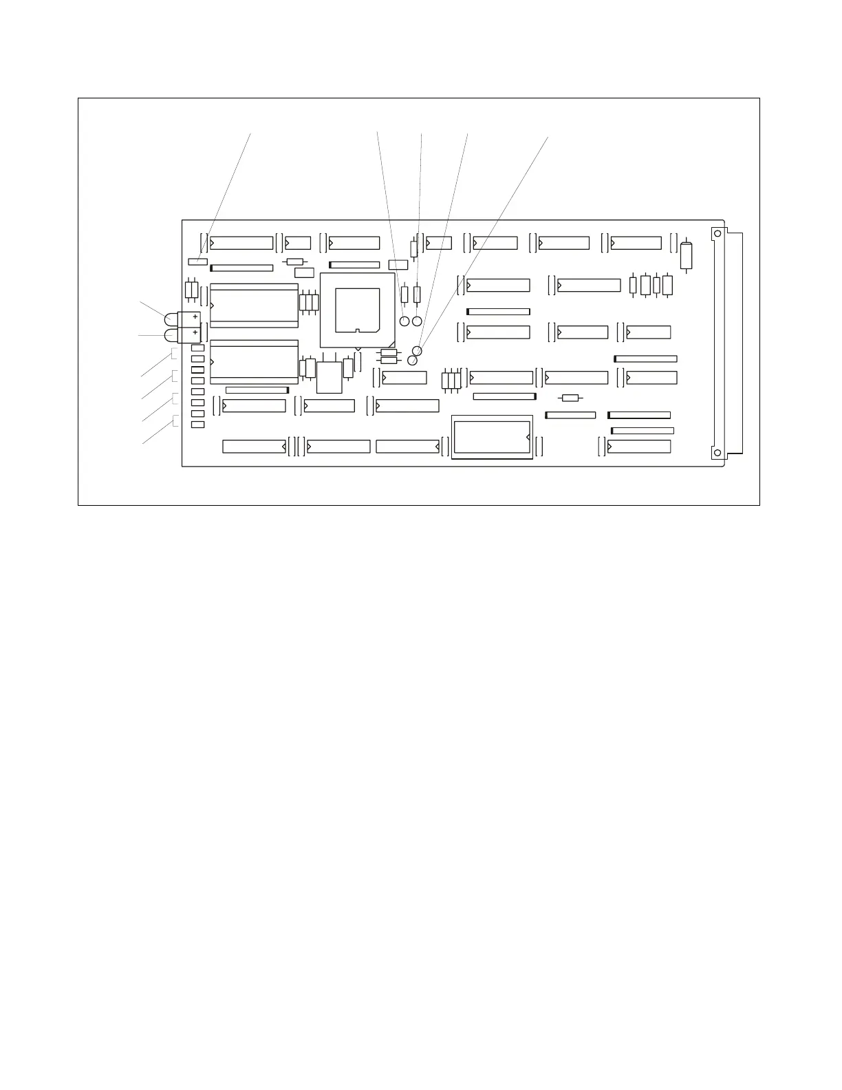
Figure 10-2. Controls and indicators, RFL 9300 supervisor controller module
CONFIGURATION JUMPERS
J1 Selects operating frequency: Position A for 60 Hz, Position B for 50 Hz.
J2 Selects terminal configuration: Position C for two-terminal, Position D for three-terminal.
J3 Selects ACT current: Position E for 5 Arms, Position F for 1 Arms.
J4 Set at the factory according to the EPROM devices installed for U14 and U15. Position J is
used for 64K devices, and Position K for 256K devices. Do not change the setting of this
jumper in the field, unless U14 and U15 are being replaced with another device type.
J5 Selects 3-pole or single pole tripping: Position G for 3-pole, Position H for single pole.
TEST TURRETS
TP1 Monitoring point for positive-going watchdog timer strobe signal.
TP2 Monitoring point for the system clock signal. This will be a 2.0-kHz signal if J1 is in Position A,
or 1.667-kHz signal if J1 is in Position B. If the relay is configured for 3-terminal operation, the
system clock is phase locked at 33 x the line frequency in Hz.
TP3 Monitoring point for the low-going READY/BUSWIDTH signal that signifies the start of a mem-
ory mapped I/O bus cycle.
TP4 Measuring point for the microcontroller's CLKOUT signal. It should be 8 MHz, or half the inter-
nally-generated clock frequency.
RFL 9300 RFL Electronics Inc.
October 29, 2001 10 - 2 (973) 334-3100