TB
TP 3
TP 6
TP 7
TP 2
TP 5
TP 1
TP 4
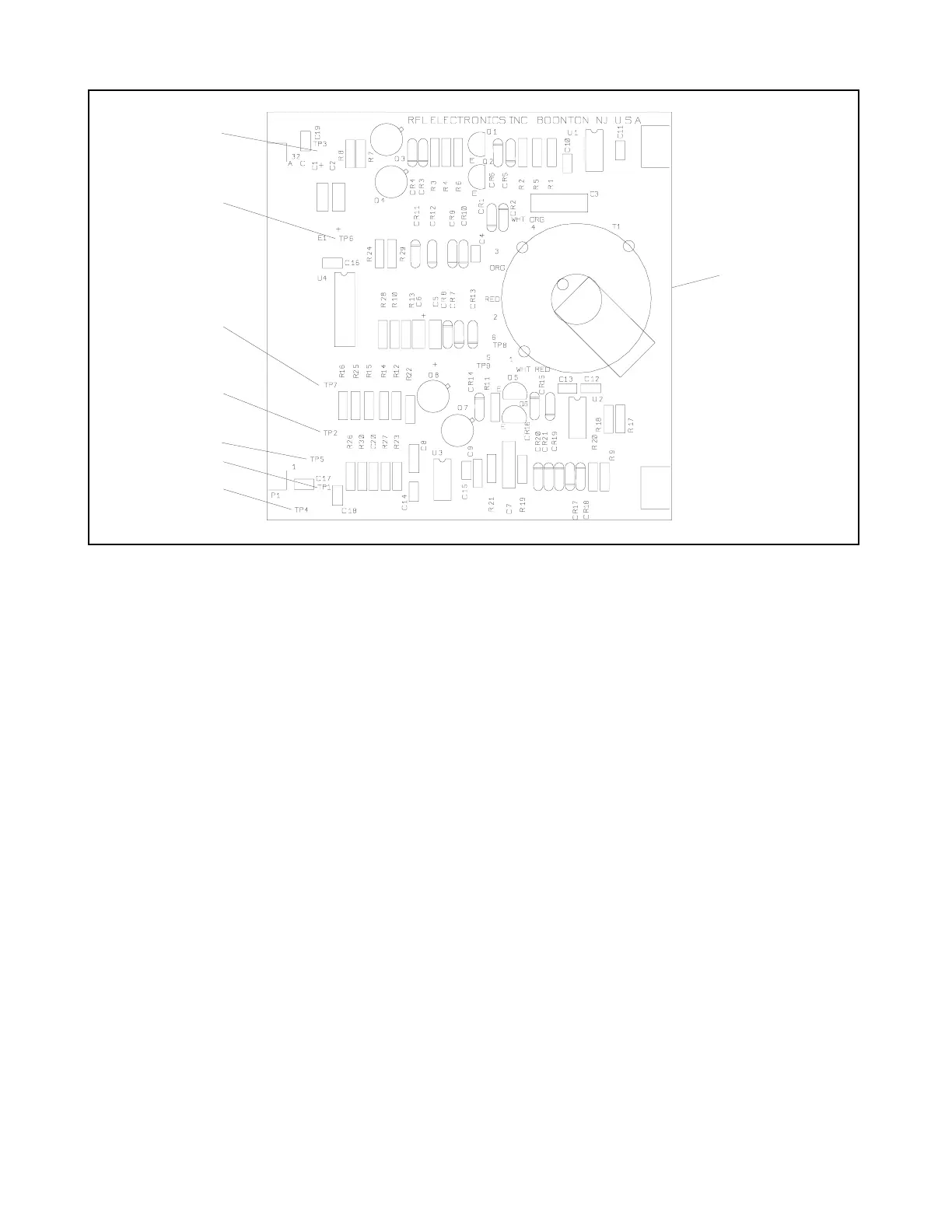
Figure 11-2. Controls and indicators, RFL 93B ACT I/O Auxiliary Current Transformer I/O Module
TP5 Monitoring point for PWR UP RESET line.
TP6 Monitoring point for high-current buffer output.
TP7 Monitoring point for full-wave rectifier output.
11.3 THEORY OF OPERATION
The RFL 93B ACT I/O Auxiliary Current Transformer I/O Module is an active current transformer that converts
power system currents to voltages. These voltages are passed on to the phase controller modules for further
processing. Normal steady-state input currents are 5 A
rms
@ 60 Hz, and currents during power system distur-
bances could be as high as 250 A
rms
. The RFL 93B ACT I/O uses the following formula for output scaling:
V
out
= I
in
/ 6.35
The RFL 93B ACT I/O uses a flux cancellation technique that creates a near-perfect current transformer.
The RFL 93B ACT I/O contains a current transformer, a sense amplifier with high-current buffer, an analog
switch, a current-to-voltage converter with high-current buffer, and a buffered 200-Hz low-pass filter. A block
diagram of the RFL 93B ACT I/O appears in Figure 11-3.
RFL 9300 RFL Electronics Inc.
March 26, 1999 11 - 2 (973) 334-3100