24.4 THEORY OF OPERATION - SOFTWARE
24.4.1 INITIALIZATION OF THE SINGLE-POLE LOGIC
The Display Controller works closely with the Supervisor Controller to initialize and monitor the interface be-
tween the RFL 9300 relay and the Single-Pole chassis.
The Supervisor will test SP_DETECT (JP1-25) to determine if the Single-Pole chassis is present in the system.
If it is present, the generic Single-Pole Chassis alarm (Alarm #54) will become active and the alarm message
will be transmitted to the Display Controller using DISP_DATA (JP1-5). When the Display Controller is powered,
it transmits at least one 16-bit initialization message to the Single-Pole chassis whether it’s present in the sys-
tem or not. This message will contain trip targets, current sense targets, and the trip release code all previously
stored in non-volatile ram. The message will also contain a bit signifying whether the system is configured as
single-pole or three-pole and a bit signifying whether or not the targets should be loaded or ignored. The Display
Controller will continue to send the initialization message to the Single-Pole chassis at 750ms intervals for as
long as the alarm remains active. If the Single-Pole chassis is not detected by the Supervisor the alarm will
never become active and no further initialization messages will be sent. The format of the initialization message
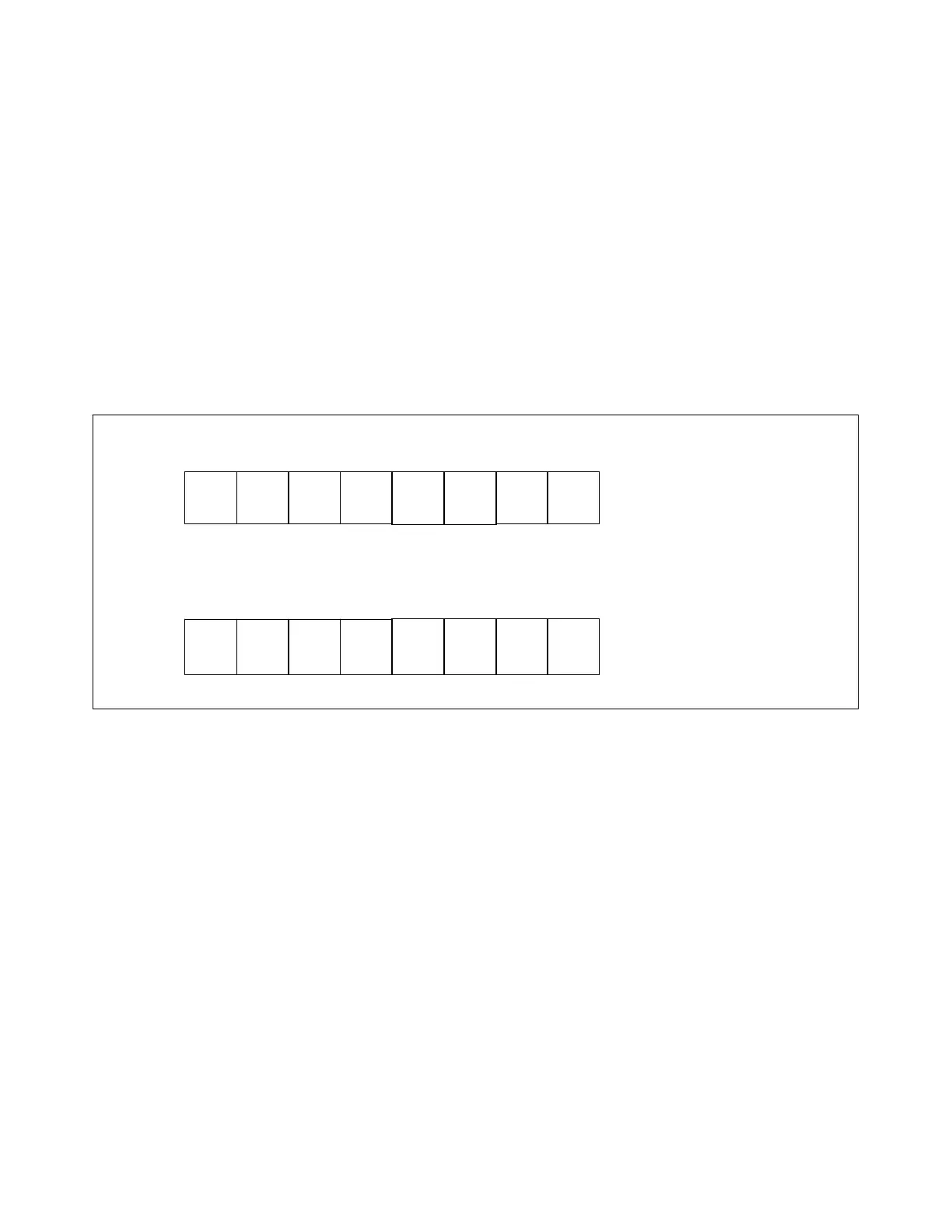
word is shown in Fig. 24-4. The Display Controller provides a clock signal on DISP_CLK (JP1-6) to enable the
single-pole logic to clock-in the message bits on the rising edge of each clock cycle.
Current Sense Targets Trip Release Code
0 1 2 3 4 5 6 7
CS CS CS CS CS CS TR TR
A1 A2 B1 B2 C1 C2 Bit 0 Bit 1
MSB bits 7-15
Start Bit Trip Targets Mode Not Assigned
0 1 2 3 4 5 6 7
1 A B C 1=3p 1 1 Load
Trip Trip Trip 0=1p Targets
LSB bits 0 - 7
Note: This message is transmitted
in the bit order shown i.e. lsb first.
Figure 24-4. Target Message Word sent from the Display Controller to the Single-Pole Chassis
• Start Bit Bit 0 Always a logic 1
• Target Bits Bits 1- 3 (Phase [x] Trip) , 8 - 13 (Phase [x] DC Current Sense - read from NV RAM)
1 = Target On
0 = Target Off
• Mode Bit Bit 4 (read from NV RAM)
0 = Relay configured for single-pole trip
1 = Relay configured for three-pole trip
• Load Targets Bit 7
1 = Ignore target & mode bits
0 = Accept all bits
• Trip Release Code Bits 14-15 (read from NV RAM)
Bit 14 Bit 15
0 0 Trip released when current sensor and trip signals no longer active.
Display indication for this code is: CS+TRIP
0 1 Trip released 100ms after trip signal is no longer active.
Display indication for this code is: TRIP+100
1 0 Trip released without delay after trip signal is no longer active
Display indication for this code is: TRIP+0
1 1 Not used
RFL 9300 RFL Electronics Inc.
August 25, 2000 24 - 8 (973) 334-3100