18.4 CONTROLS AND INDICATORS
Figures 18-2 through 18-4 show the locations of all controls and indicators on the RFL 93 FT/FR single width
fiber optic I/O modules. These controls and indicators are described below.
Controls
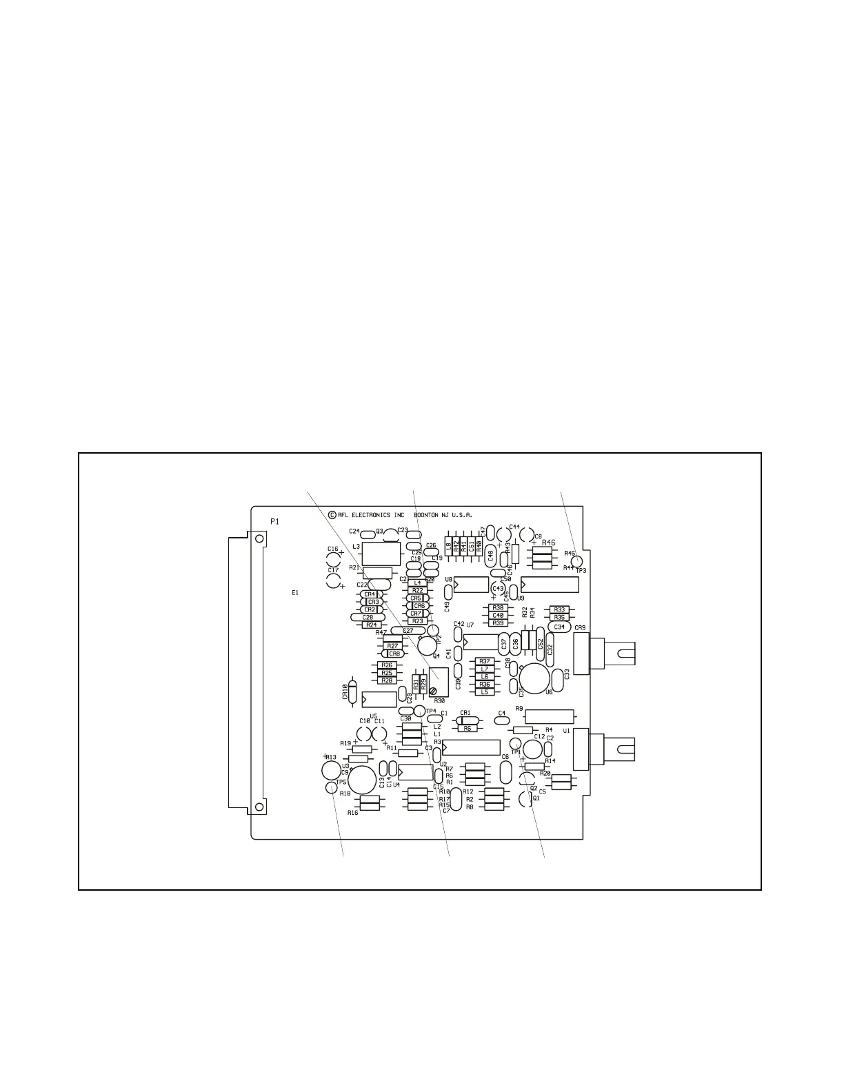
R30 Potentiometer used at factory for adjusting Avalanch Photo Diode (CR9) bias current
Test Turrets
TP1 Monitoring point for LED emitter (U1) drive current
TP2 Monitoring point for high voltage supply
TP3 Monitoring point for REC_DATA signal
TP4 Monitoring point for Avalanch Photo Diode (CR9) bias current. 25mV is equivalent to
about 0.5nA, and 150mV is equivalent to about 3.0nA.
TP5 Ground
TP 3
TP 5 TP 4
TP 1
Figure 18-2. Controls and indicators, RFL 93 FT/FR I/O-8M single width fiber optic I/O module
RFL 9300 RFL Electronics Inc.
January 19, 2005 18 - 4 (973) 334-3100