SECTION 24: SINGLE POLE CHASSIS
RFL 9300
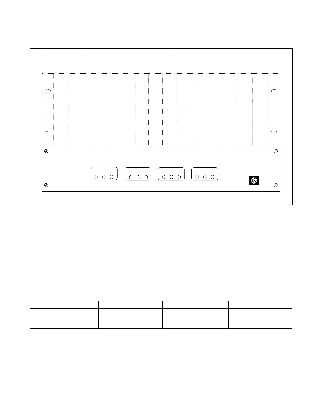
Single Pole Option
RFL Electronics
STATUS PHASE A PHASE B PHASE C
THREE SINGLE TRIP
POLE POLE DISABLE TRIP TC1 TC2 TRIP TC1 TC2 TRIP TC1 TC2
Figure 24-1. Typical RFL 9300 Single Pole Chassis, front panel view
24.1 DESCRIPTION
Single Pole Tripping is an optional feature of the RFL 9300, which requires an additional chassis mounted be-
low the existing RFL 9300 chassis. The Single Pole Chassis contains all of the circuitry required for Single Pole
Tripping, which allows phase A, B or C to trip independently of the other two phases. A front panel view of the
RFL 9300 Single Pole Chassis is shown in Figure 24-1. A rear panel view of the RFL 9300 Single Pole Chassis
is shown in Figure 24-3.
Table 24-1 provides general information about the Single Pole Chassis, Tables 24-2 and 24-3 are lists of re-
placeable parts, Figures 24-6 and 24-8 are component locator drawings, and Figures 24-7 and 24-9 are sche-
matic diagrams.
Table 24-1. RFL 9300 Single Pole Chassis, General Information
Model Number
Assembly Number Width Height
9300 CC
SINGLE POLE TRIP
106700
17.25 in
(43.82 cm)
3.375 in
(8.57 cm)
24.2 CONROLS AND INDICATORS
The controls and indicators for the Single Pole Chassis consist of front panel LED indicators, rear panel terminal
blocks, and circuit board test points. Figures 24-2, and 24-3 show the locations of all controls and indicators on
the Single Pole Chassis. Note that the front panel has LEDs only, and the rear panel has terminal blocks only.
RFL 9300 RFL Electronics Inc.
August 25, 2000 24 - 1 (973) 334-3100