1
2
3
4
5
6
7
8
1
2
3
4
5
6
7
8
R
E
L
A
Y
I/O
P.S.
1 +
2 -
TB1
TB2
TB3
CCS
TRIP-1
CCS
TRIP-2
CCS
AUX-1
CCS
AUX-2
DTT-1
DTT-2
CCS
AUX-3
CCS
AUX-4
IRIG-B
J1
RS-232
J1
TB1
IRIG-B TB2 TB3
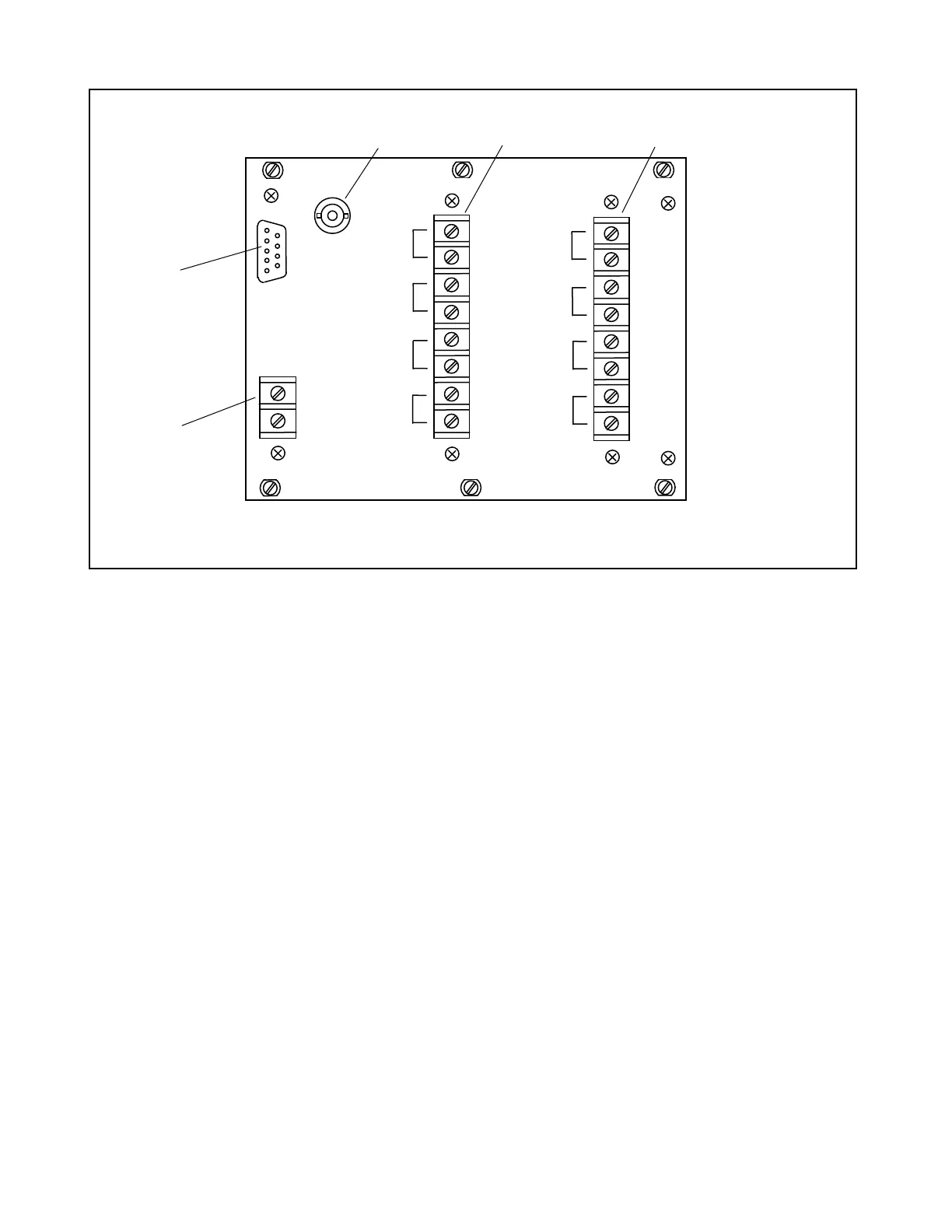
Figure 20-2. Rear panel connectors and terminal blocks, RFL 93B Relay I/O Module
20.2.1 REAR PANEL CONNECTORS AND TERMINAL BLOCKS (See Figure 20-2)
J1 9-pin D-subminiature (DE-9) connector for RS-232 interface (future enhancement).
IRIG-B BNC connector for IRIG-B input.
TB1 Input Power:
TB1-1 Station Battery +
TB1-2 Station Battery -
TB2 DTT Output Connections:
TB2-1 and TB2-2 DTT-1
TB2-3 and TB2-4 DTT-2
CCS Output Connections:
TB2-5 and TB2-6 CCS AUX-3
TB2-7 and TB2-8 CCS AUX-4
TB3 CCS Output Connections:
TB2-1 and TB2-2 CCS TRIP-1
TB2-3 and TB2-4 CCS TRIP-2
TB2-5 and TB2-6 CCS AUX-1
TB2-7 and TB2-8 CCS AUX-2
RFL 9300 RFL Electronics Inc.
May 5, 2002 20 - 2 (973) 334-3100