JX”r
+
Er”
-
El L
Em M
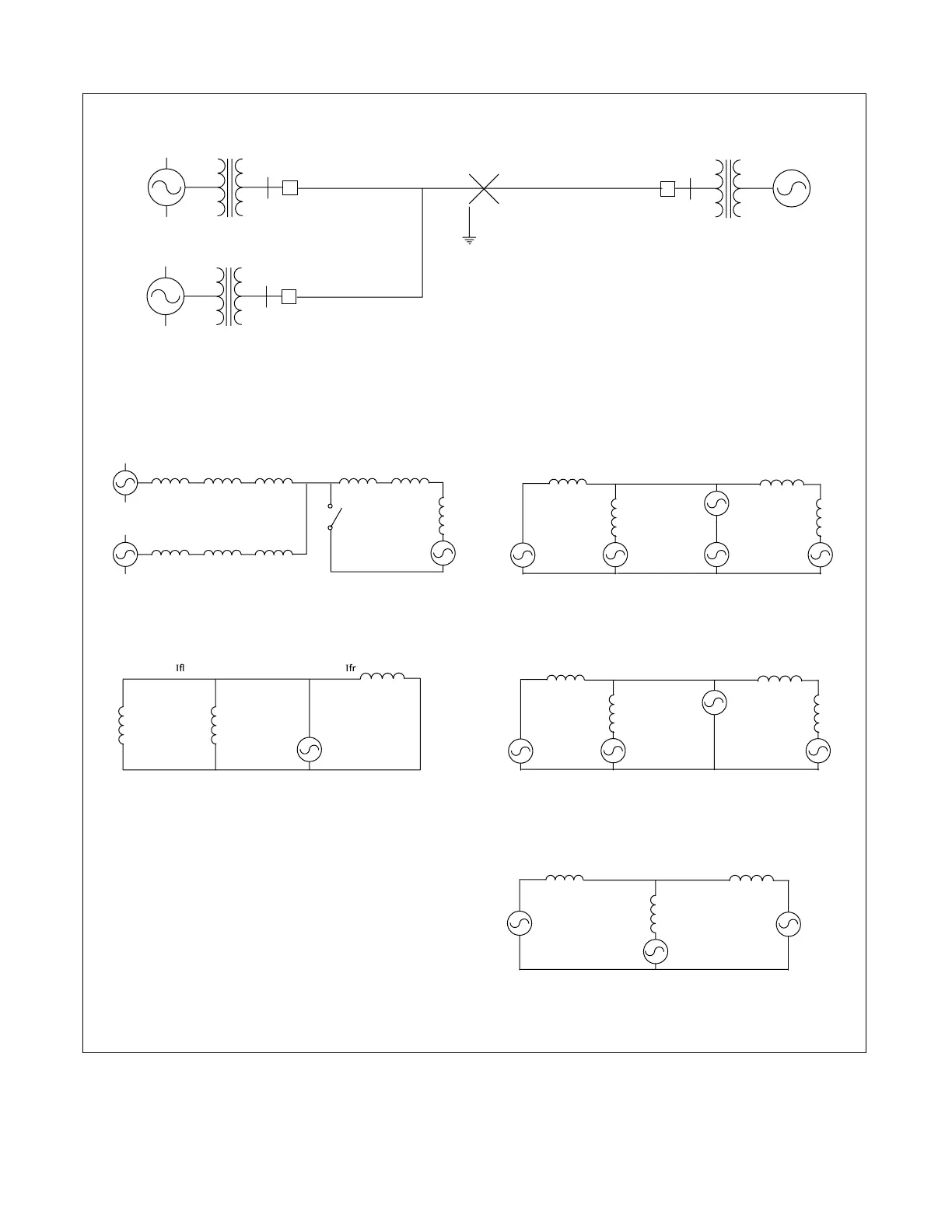
Single line diagram of system
Three phase fault
R Er
T1
T2
+ El”
-
+ Em”
-
JX”l JXT1 JXl
JX”m JXT3 JXm
Fault
JX”r
+
Er”
-
a) Three-phase short circuit b) Short circuit represented by two opposing voltage sources
c) Application of superposition d)
e) Vf set equal to prefault voltage at fault
”
”
Ifm”
↑
JXm-thevenin
JXl-thevenin
JXr-thevenin
↓ If” - fault current
-
Vf
+
Ill”→ ←Irl”
JXl-thevenin + JXr-thevenin
↑ Vf
Iml” JXm-thevenin - JX”r
+
El”
-
+
E1”
-
+
Em”
-
Vf
+
Il”→ ←Ir”
J(XT1+Xl+X”l) + J(XT2+Xr)
↑ J(XT3+Xm+X”m) Vf
Im” -
JXI-thevenin
+
E1”
-
JXr-thevenin
↑
Iml” JXm-thevenin
+
Em”
-
Iload – pre-fault load
→
+
Er”
-
+
Em”
-
+
”
f
Figure 3-8. Prefault load subtraction eliminates generator angles
RFL 9300 RFL Electronics Inc.
August 25, 2000 3 - 7 (973) 334-3100