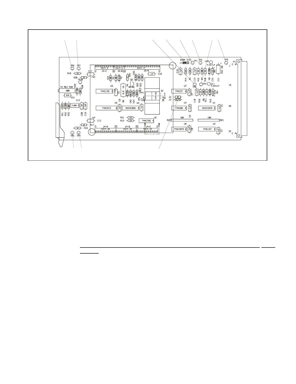
TP 5 TP 4
J2
J3
Figure 14-2. Controls and indicators, RFL 9300 modem module
JUMPERS
J1 Controls attenuation between RFL LC I/O module and RFL 93B MO. Place in Position
A for no attenuation, or Position B for 3 dB of attenuation.
J2, J3 These jumpers control the polarity of the RD (read) line:
J2 in, J3 out - Normal polarity (RD).
J2 out, J3 in - Inverted polarity (/RD).
J2 and J3 are set at the factory according to the requirements of the plug-on modem card.
Do not move these jumpers, unless the modem card is being replaced with a
differ-
ent type.
TEST POINTS
TP1 Monitoring point for RX IN; this is an analog signal that should be around -18 dBm if
jumper J1 is in Position A.
TP2 Monitoring point for +12-volt regulator; should be between +11.4 and +12.6 volts.
TP3 Monitoring point for -12-volt regulator; should be between -11.4 and -12.6 volts.
TP4 Monitoring point for RX clock; this is a digital signal that varies between 0 and 5 volts at a
rate of 7.2 Kbps.
TP5 Monitoring point for RX data (recovered data); this is a digital signal that varies between
zero and 5 volts.
RFL 9300 RFL Electronics Inc.
May 1, 1998 14 - 2 (973) 334-3100