7.4.11 INTERNAL A-G FAULTS WITH REMOTE BREAKER OPEN
In 2-terminal mode the RFL 9300 will transmit a Weak Current Message (WCM) whenever the local breaker is
open (no AC line current >1/8 A peak detected for 40 ms by all phase controllers). When an RFL 9300 re-
ceives a WCM, it will allow tripping if the local current is greater than the bias setting. A single fault detector,
on the phase in question, satisfies the fault detector requirement for the 3I0 controller. This applies to 2-
terminal mode only and only applies to the 3I0 controller. The phase A, B and C controllers still require 2 fault
detectors.
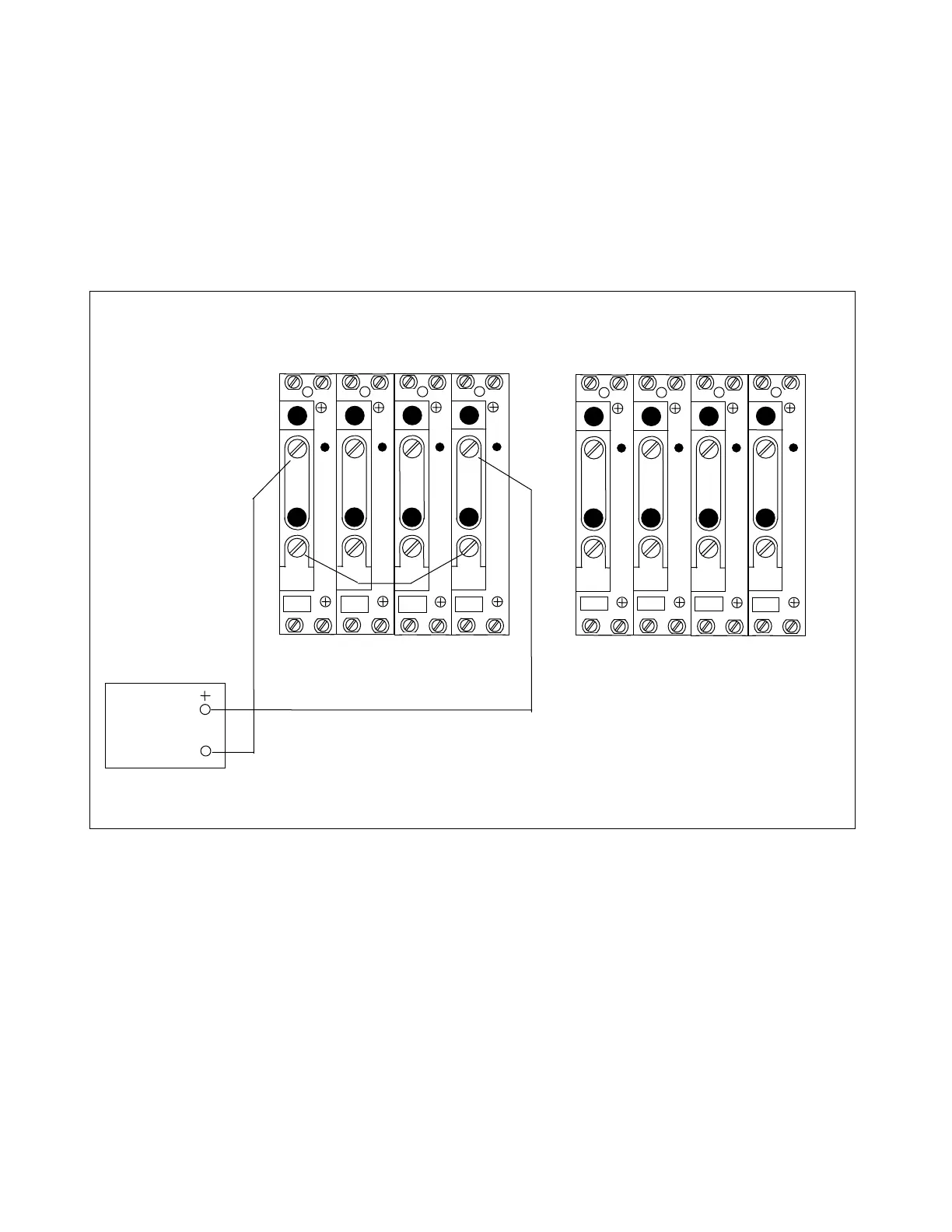
1. Connect the test circuit shown in Figure 7-11.
AC
CURRENT
SOURCE
TB4
TB5
A
C
T
A
C
T
TB6
TB7
A
C
T
A
C
T
3I
0
I
C
I
B
I
A
1 1 1 1
2 2 2 2
TB4
TB5
A
C
T
A
C
T
TB6
TB7
A
C
T
A
C
T
3I
0
I
C
I
B
I
A
1 1 1 1
2 2 2 2
LEFT TERMINAL RIGHT TERMINAL
Figure 7-11. Test connections simulating an internal A-G fault with breaker open at the right terminal
2. Slowly increase the test current.
At 0.5 amperes, the ground fault detector will operate. At 1.5 amperes, both relays will
trip and their G target indicators will light. The RFL 9300 at the right terminal will trip on
a received CCT-U message.
It is useful to permit the RFL 9300 at the right terminal to attempt to trip the breaker,
even though the lack of any ac line current indicates that the breaker is open. This trip
attempt will close the tripping auxiliary relay contacts, and they can serve as breaker
failure initiate inputs.
RFL 9300 RFL Electronics Inc.
October 20, 2004 7 - 19 (973) 334-3100