SECTION 21. ALARM I/O MODULE
ALARM
I/O
N.C.
N.O.
C.
N.C.
N.O.
C.
TB8
1
2
3
4
5
6
+
-
+
-
+
-
TB9
ALARM I/O SYSTEM CONFIG
VOLTAGE 48 110/120 220/250
J5 OPEN CLOSED
J6 OPEN CLOSED
DO NOT CLOSE J5 & J6 FOR
220/250V SYSTEMS
CHANGE JUMPER SETTINGS ONLY
WHEN POWER IS OFF
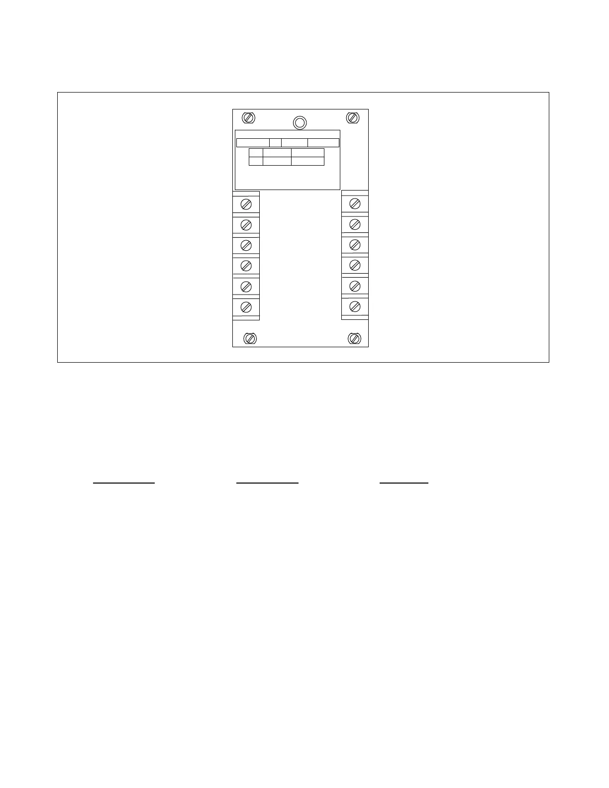
Figure 21-1. RFL 93 Alarm I/O Module
21.1 DESCRIPTION
The RFL 93 Alarm I/O Module (Fig. 21-1) is an interface module mounted at the rear of all RFL 9300 units. It
provides connections for DTT input, 89B disconnect switch input, reclose block output, and alarm relay outputs.
There are three types of RFL 93 Alarm I/O modules as follows:
Assembly No. Nomenclature Application
104775-5 93 Alarm I/O Operates on 48V, 125V or 250V
104775-6 93 Alarm I/O (24V) Operates on 24V only
104775-7 93 Alarm I/O (48/110/220) Operates on 48V, 110V or 220V
21.2 CONTROLS AND INDICATORS
The controls and indicators on the 104775-5 and 104775-7 modules consist of two terminal blocks (TB8 and
TB9) and six jumpers (J1 to J6). The controls and indicators on the 104775-6 module consist of two terminal
blocks (TB8 and TB9) and two jumpers (J5 and J6). These controls and indicators are described below. The
terminal blocks are mounted on the rear panel, and are accessible with the RFL 93 Alarm I/O installed in the
RFL 9300 chassis. The jumpers can only be accessed with the Alarm I/O module removed from the chassis.
The location of the terminal blocks and jumpers is shown in Figure 21-2.
>> text continues on page 21-3 <<
RFL 9300 RFL Electronics Inc.
May 5, 2002 21 - 1 (973) 334-3100