7.4.14 OSCILLOGRAPHY TEST
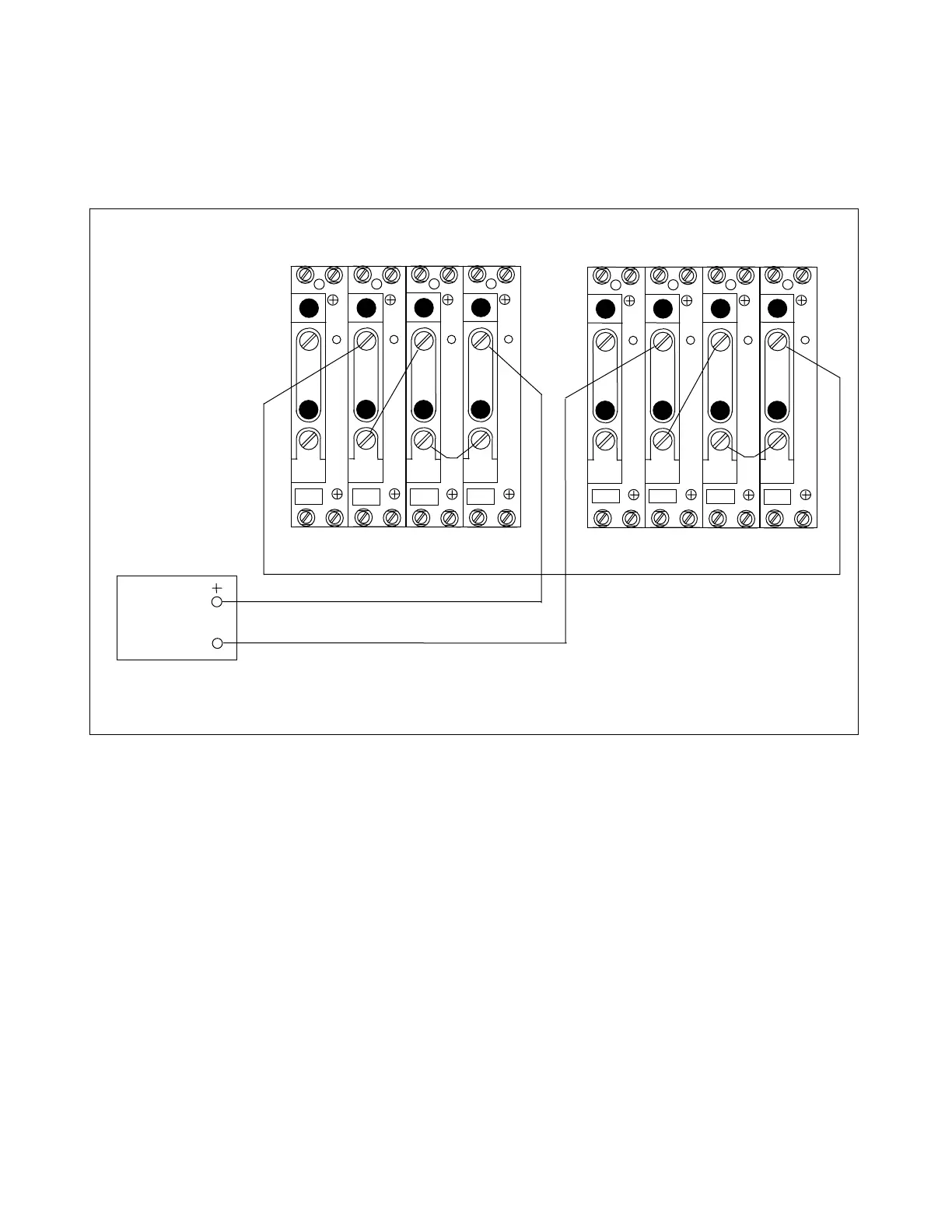
1. Connect the test circuit as shown in Figure 7-19.
AC
CURRENT
SOURCE
3I
0
I
C
I
B
I
A
3I
0
I
C
I
B
I
A
2 2 2 2
TB4
TB5
A
C
T
A
C
T
TB6
TB7
A
C
T
A
C
T
1 1 1 1
2 2 2 2
TB4
TB5
A
C
T
A
C
T
TB6
TB7
A
C
T
A
C
T
1 1 1 1
LEFT TERMINAL RIGHT TERMINAL
Figure 7-12. Test connections for oscillography test
2. Apply a 3.0 ampere test current.
3. Connect an RS-232 cable from the front or rear RS-232 connector to a PC equipped with Microsoft
Windows HyperTerminal emulator. This procedure is described in Section 6 under the heading
“ACCESSING THE RFL 9300 FROM A PC OR TERMINAL”.
4. Establish communication between the RFL 9300 and your PC or laptop. When communication has
been established the RFL 9300 will send the following prompt to your PC:
9300>
5. Type “S” [ENTER] to enter the sequence of events menu as shown in Figure 6-11.
6. Type “F” [ENTER] to force an oscillography trip event.
RFL 9300 RFL Electronics Inc.
October 20, 2004 7 - 21 (973) 334-3100