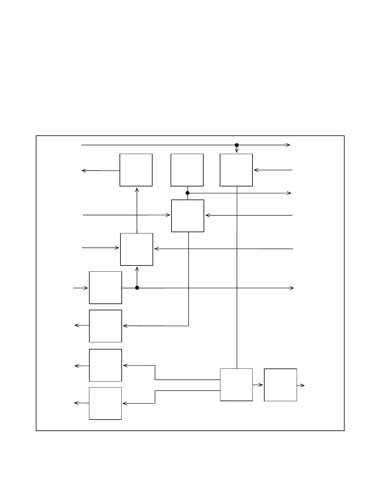
RS-422 TX Data from CC#1 is routed to the primary FT/FR where it is converted to TTL. The TXCONTR signal
is a logic one. This signal is pulled to a logic zero when CC#2 is installed. In hot standby mode CC#2 is not
used. A logic one on TXCONTR steers TX_DATA in the primary FT/FR to the modulator and the primary FT/FR
I/O. TX_DATA is routed via the backplane to the secondary FT/FR where the identical method is used to steer
TX_DATA to the secondary FT/FR I/O. We now have redundant TX_DATA being transmitted over two separate
cables.
On the receive side, when the secondary FT/FR module is installed, a grounded pin on the module will pull the
TEST input on CC#1 low, signaling Hot Standby mode. In this mode the STANDBY control line will become ac-
tive. When the line is low the primary FT/FR is selected and when it is high the secondary FT/FR is selected.
The receive data from the secondary FT/FR is routed to the primary FT/FR via the backplane. The switching of
receive data, primary or secondary, is done on the primary FT/FR. Refer to the Fiber Optic signal routing block
diagram.
FROM FIBER
I/O MODULE
TO FIBER
I/O MODULE
RXD_OUT
A21
RXD_IN
C21
TXCLKOUT
A18
TXCLH_IN
C18
TXD_IN
A22
XTX_ DATA
C22
RX CARRIER
ALARM
STANDBY
A15
TXCONTR
C15
TX_DATA
(RS422)
TX_CLK
(RS422)
RX_DATA
(RS422)
RX_CLK
(RS422)
LINE
RECEIVER
LINE
DRIVER
LINE
DRIVER
LINE
DRIVER
ACTEL
DEMOD-
ULATOR
OUT OF
LOCK
DETECTOR
ACTEL
MODU-
LATOR
LOCAL
TX CLOCK
RX DATA,
DATA
SELECTOR
(P/O ACTEL)
TX CLOCK,
DATA
SELECTOR
(P/O ACTEL)
TX DATA,
DATA
SELECTOR
(P/O ACTEL)
Figure 17-3. Block diagram, RFL 93B FT/FR single width fiber optic transceiver module
RFL 9300 RFL Electronics Inc.
May 1, 1998 17 - 7 (973) 334-3100