RFL 9300 RFL Electronics Inc.
August 9, 2001 9 - 2 (973) 334-3100
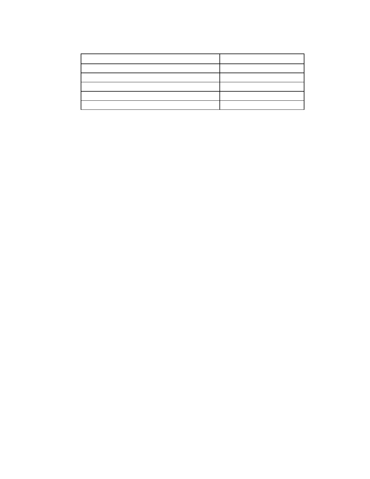
Table 9-1. RFL 93B Display Module, general information
Model Designator
Assembly Number
Display Module (93B DISPLAY) horizontal 106320-2
Display Module (93B DISPLAY) vertical 106320-3
Display Controller Board 106325-2
Oscillography Board 106330
Front Panel Assembly 106335
4. Reads the TRIP/DTT inputs and the current sense inputs on the oscillography board.
5. Retrieves IRIG-B values from the oscillography board for time tagging events.
6. Supplies trip commands to the oscillography board to trigger oscillography storage.
7. Retrieves oscillography values for downloading.
8. Operates the audible sounder on the oscillography board.
9. Stores information on the programmable variables and the state of all sealed-in LED indicators in non-
volatile RAM.
10. Communicates with the RFL 93B SV Supervisor Module over an RS-485 interface bus.
11. Communicates with the outside world through a front or rear RS-232 port.
12. Controls the TRIP DISABLE/ENABLE line.
13. Uses the Trip Release algorithm programmed by the operator to unlatch output trip signals.
9.2.2 CONTROLS AND INDICATORS
Figure 9-2 shows the location of all controls and indicators on the display controller. These controls and indica-
tors are described below. Those described as front-panel controls are accessible with the display module in-
stalled in the chassis; all others are accessible when the display module is removed from the chassis, or is
placed on card extenders.
LED INDICATORS
DS301 PROTECTION - Front-panel indicator; lights red when protection is disabled; the color changes to
green when protection is enabled.
DS302 TRIP - Front-panel indicator; four individual LEDs that light red to show which phase(s) are faulted;
Phase A (A), Phase B (B), Phase C (C), or ground (G).
DS303 DTT TX - Front-panel indicator; lights red when a DTT signal is sent to the remote terminal.
DS304 DTT RX - Front-panel indicator; lights red when a DTT signal is received from the remote terminal.
DS305 BACKUP - Front-panel indicator; lights red when the RFL 9300 goes into the back-up mode. This
will happen when Parameter 20 (BACKUP) has been enabled, and a communications failure oc-
curs. (The RFL 9300's alarm relay will also change states.)