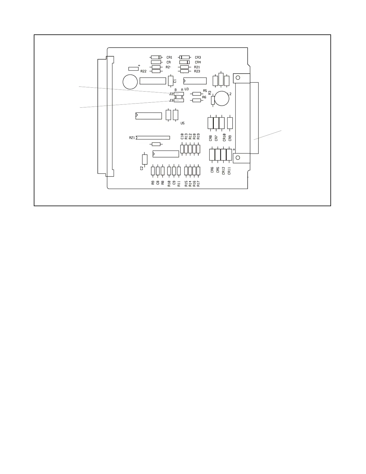
J2
J3
J
Figure 16-2. Controls and indicators, RFL 93 DD Direct Digital I/O Module
REAR-PANEL CONNECTOR
J1 Rear-panel RS-449 connector; accepts RS-422 signals. The following pins are supported; all
other pins are not connected:
Pin RS-449 CCITT X.21
No. Signal Signal
5 ST + Signal Timing A
23 ST - Signal Timing B
8 RT + Signal Timing A
26 RT - Signal Timing B
6 RD + Receive A
24 RD - Receive B
7 RT + Control B (+5V)
25 RT - Control A (GND)
19 SG Signal Ground
22 SD - Transmit B
4 SD + Transmit A
JUMPERS
J2 J2 sets the polarity of the SEND timing signal. Position A selects inverted polarity, and Position
B selects normal polarity. J2's setting will depend on the DCE being connected to the RFL
9300. Try to use the RFL 9300 with J2 in Position B; if the SEND timing is not working properly,
move J2 to Position A.
RFL 9300 RFL Electronics Inc.
May 1, 1998 16 - 2 (973) 334-3100