8.2.3.4.3 Internal Three-Phase Faults
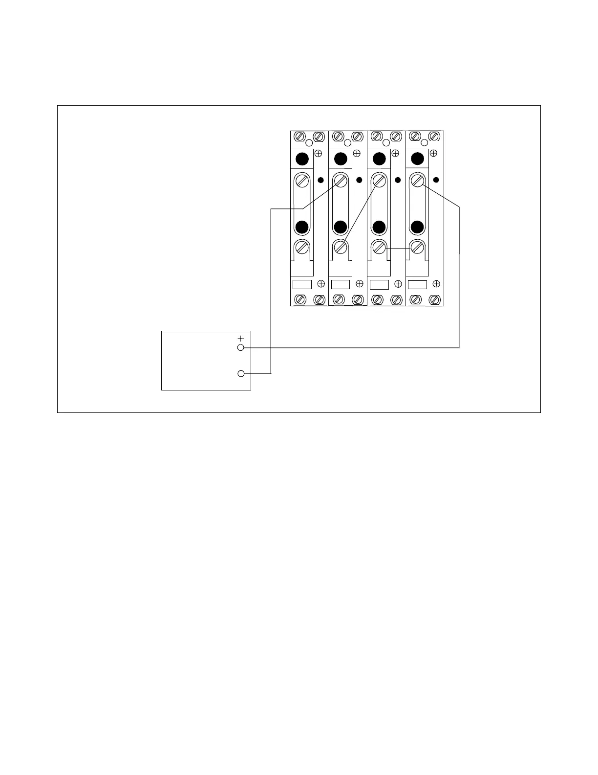
1. Connect the equipment as shown in Figure 8-4.
TB4
TB5
A
C
T
A
C
T
TB6
TB7
A
C
T
A
C
T
1
1 1 1
2
2
2
2
3I
0
I
C
I
B
I
A
AC
CURRENT
SOURCE
Figure 8-4. Test connections simulating an internal three-phase fault
2. Apply test currents of various levels.
Results should be similar to the results obtained for the A-B fault simulation, ex-
cept all three phase targets (A, B, and C) should now operate. The reclose block
output (terminals TB9-1 and TB9-2) also should operate.
RFL 9300 RFL Electronics Inc.
October 20, 2004 8 - 16 (973) 334-3100