SECTION 9: DISPLAY MODULE
1 2 3
4
5 6
7 8 9
0
ENT
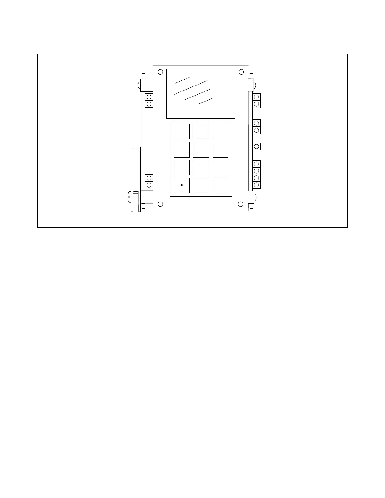
Figure 9-1. RFL 9300 display module for horizontal chassis
9.1 INTRODUCTION
The RFL 9300 display module (93B DISPLAY), shown in Figure 9-1, serves as the user interface to the RFL
9300. Entries on its keyboard place the RFL 9300 into one of its four operating modes. Programmable parame-
ters can be set by keyboard entries while the RFL 9300 is in the PROGRAM mode.
Each display module contains three main assemblies (See Table 9-1). The display controller board is described
below, the oscillography board is described in paragraph 9.3 of this section, and the front panel assembly is de-
scribed in paragraph 9.4 of this section.
9.2 DISPLAY CONTROLLER BOARD
9.2.1 DESCRIPTION
The display controller board performs the following functions:
1. Accepts inputs from the keyboard on the front panel.
2. Operates the display on the front panel.
3. Controls its LED indicators, and the indicators on the oscillography board.
RFL 9300 RFL Electronics Inc.
August 9, 2001 9 - 1 (973) 334-3100