C14
P1
C15
C16
C19
C17
C21
C22
C23
C24
C25
C26
C27
C2
J3
C12
+
R18
R17
R16
R15
R1
R4
R14
R5
R6
R11
R12
R13
R10
R8
R7
R19
J4
1
U8
RZ1
U7
U6
CR10
T2
U2
TP3
R9
U4
L3
L1
L2
U5
C4
C6
C20
C3
U3
J2
C11
+
C7
+
R3
U1
C18
C13
C5
C8
C9
C10
C1
R2
TP1
TP2
T1
CR6
CR8
CR9
CR7
CR2
CR4
CR3
CR5
CR1
J5
J1
19
8
15
R20
93-G703 ECB NO 106733 REV B
LOOP NORM
1999 RFL ELECTRONICS INC
BOONTON, NJ, U.S.A.
1
32
B
A
56K
64K
XRT6164
.0022UF
914B
74HC86N
TP 2
TP 3
TP 1
J5
R
J3
R
K2
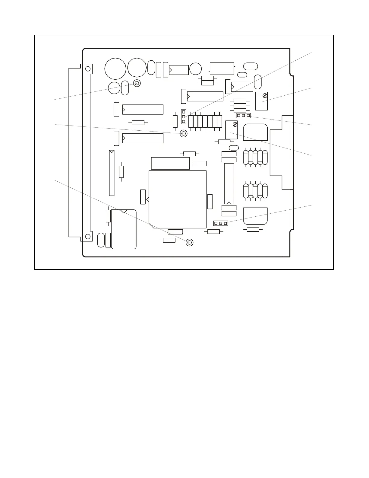
Figure 23-2. Controls and indicators, RFL 93 G.703 Interface I/O Module
REAR-PANEL CONNECTOR
J1 Rear-panel 93 G.703, DB15 connector. The following pins are supported, and all other pins are
not connected:
Pin No. 93 G.703 Signal
1 Shield Ground
2 Transmit A
4 Receive A
9 Transmit B
11 Receive B
RFL 9300 RFL Electronics Inc.
February 7, 2000 23 - 2 (973) 334-3100

 Loading...