7.4.5 INTERNAL A-G FAULTS
This procedure demonstrates "SFT" (Strong-Feed Trip) and "UHS" (Ultra-High Speed Trip). It is possible for a
UHS to cause a weak-feed trip at the station receiving the UHS message if the current at the receiving station
is less than 1.5A and there are no fault detections. Later in this section, weak-feed trip and remote breaker
open trip will be tested.
SFT requires currents of at least 0.5 Arms at both terminals. UHS operates whenever the current at one termi-
nal reaches +12 Apeak for 2 ms, and the other terminal does not have a peak reading that is more negative
than the Blocking Level (BL). The BL peak value depends on the bias setting:
BL = – (11amperes – bias amperes) peak (minimum value is 7.5A peak)
Example: For a bias setting of 3 amperes rms (4.2 A peak):
BL = – (11 amperes – 4.2 amperes) = – 6.8 A peak
BL = – 7.5 amperes peak (minimum value)
UHS is usually about 5 ms faster than SFT.
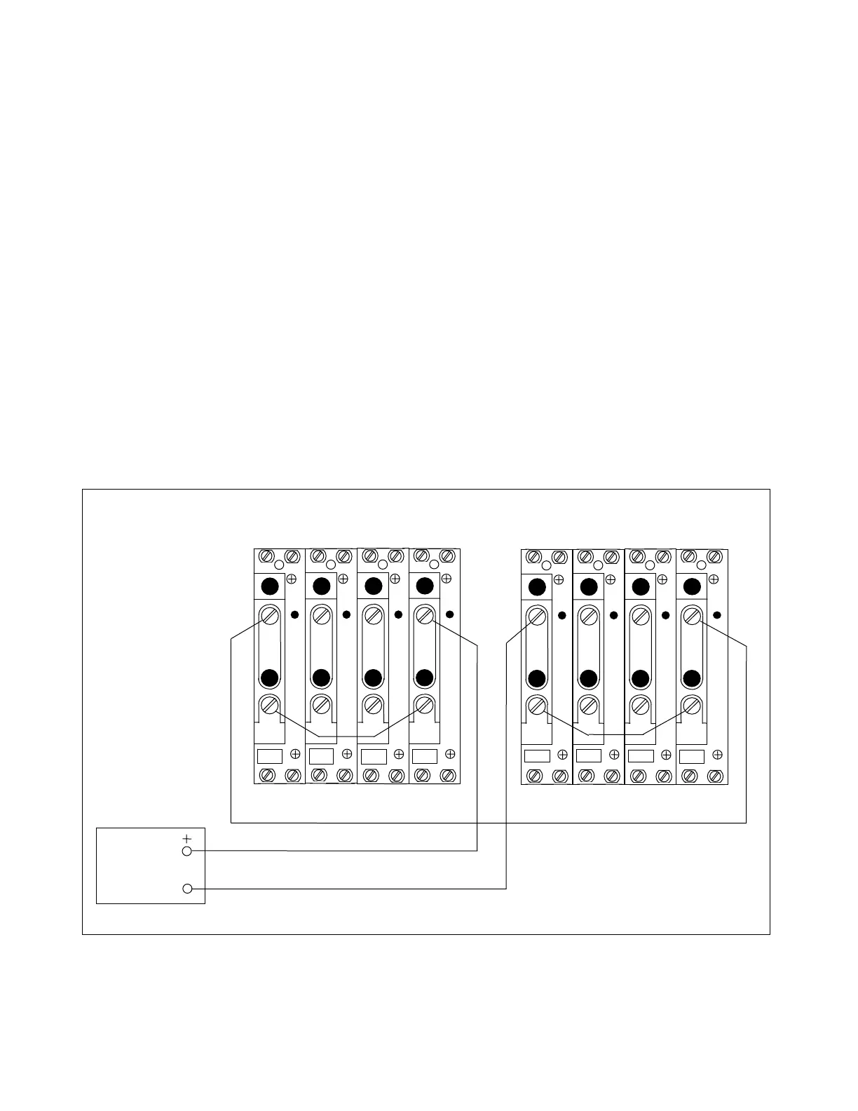
1. Connect the equipment as shown in Figure 7-7.
The current polarities at the left terminal and the right terminal are the same. This cre-
ates an "internal" current line-up for Phase A and ground.
AC
CURRENT
SOURCE
TB4
TB5
A
C
T
A
C
T
TB6
TB7
A
C
T
A
C
T
3I
0
I
C
I
B
I
A
1 1 1 1
2 2 2 2
TB4
TB5
A
C
T
A
C
T
TB6
TB7
A
C
T
A
C
T
3I
0
I
C
I
B
I
A
1 1 1 1
2 2 2 2
LEFT TERMINAL RIGHT TERMINAL
Figure 7-7. Test connections simulating an internal A-G fault
RFL 9300 RFL Electronics Inc.
October 20, 2004 7 - 12 (973) 334-3100