SECTION 12: PHASE CONTROLLER MODULE
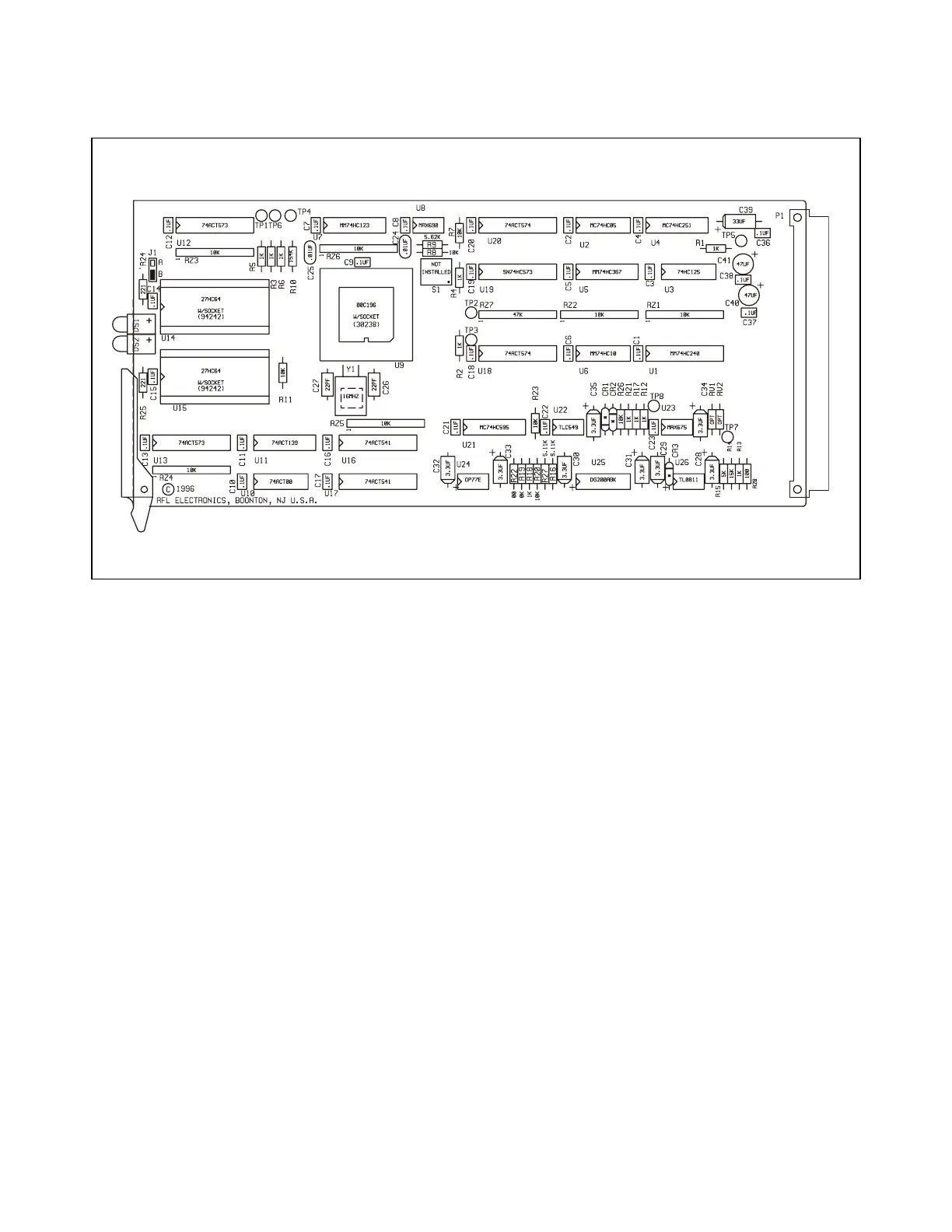
Figure 12-1. RFL 9300 phase controller module
12.1 DESCRIPTION
The RFL 93B PC Phase Controller Module is shown in Figure 12-1. Each RFL 9300 contains four RFL 93B PC
Phase Controller modules: one for each phase, and one for ground. The phase controller modules monitor the
currents passed to them by the ACT I/O modules (Section 11), and execute the RFL 9300's protection algo-
rithms. Except for DTT (which is controlled by the RFL 93B SV module), the individual phase controller modules
make all trip/no trip decisions for the RFL 9300.
12.2 CONTROLS AND INDICATORS
Figure 12-2 shows the location of all controls and indicators on the RFL 93B PC Phase Controller Module.
These controls and indicators are described below. Those described as front-panel controls are accessible with
the RFL 93B PC installed in the RFL 9300 chassis; all others are accessible when the RFL 93B PC is removed
from the chassis, or is placed on a card extender.
LED INDICATORS
DS1 ALARM - Front-panel indicator; lights when a problem is detected in a specific phase controller module.
DS2 FD - Front-panel indicator; lights when the fault detector for that phase produces an output.
RFL 9300 RFL Electronics Inc.
March 26, 1999 12 - 1 (973) 334-3100