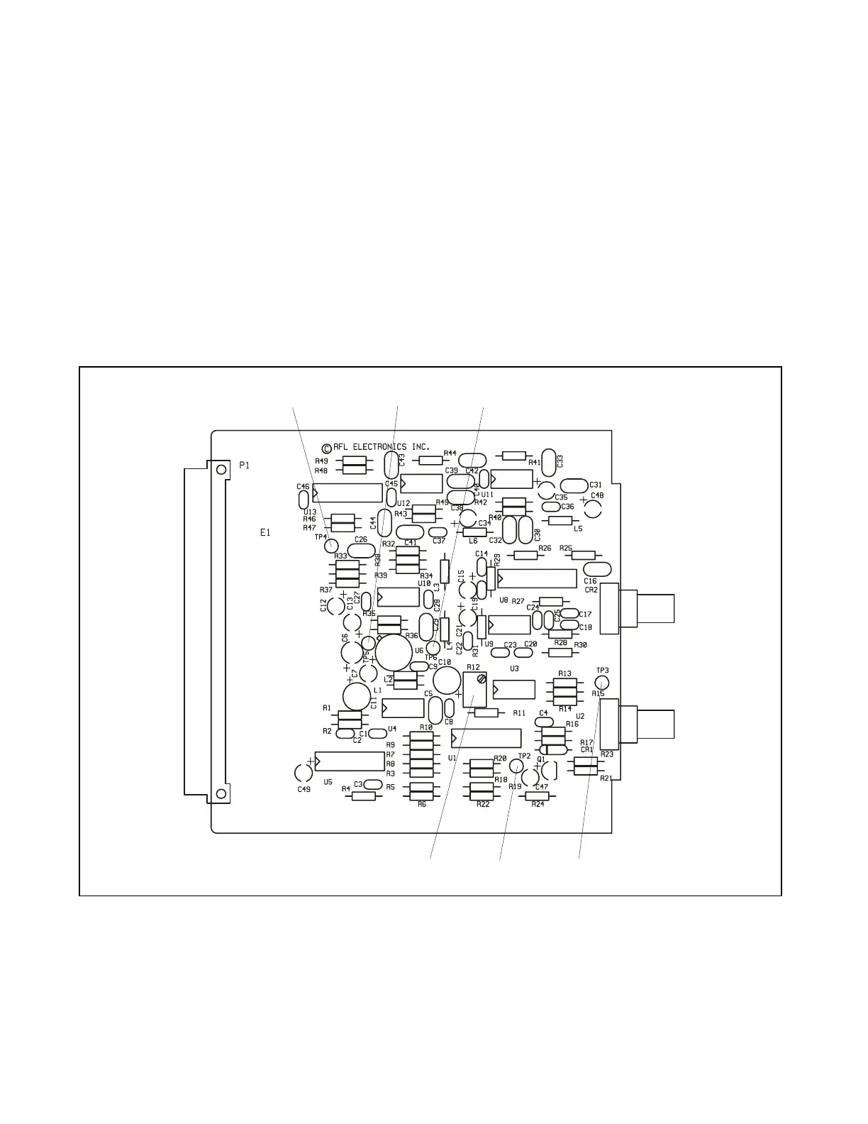
Controls
R12 Potentiometer used at factory for adjusting Avalanch Photo Diode (U2) bias current
Test Turrets
TP2 Monitoring point for LASER emitter (U2) drive signal
TP3 Monitoring point for -11Vdc source
TP4 Monitoring point for REC_DATA signal
TP5 Monitoring point for a voltage that is proportional to the light level into photo diode CR2.
The voltage can vary from about 0 to 10Vdc.
TP6 Ground
R12
TP 2 TP
Figure 18-4. Controls and indicators, RFL 93 FT/FR I/O-13SL and 15SL single width fiber optic I/O modules
RFL 9300 RFL Electronics Inc.
January 19, 2005 18 - 6 (973) 334-3100