SECTION 20: RELAY I/O MODULE
1
2
3
4
5
6
7
8
1
2
3
4
5
6
7
8
R
E
L
A
Y
I/O
P.S.
1 +
2 -
TB1
TB2
TB3
CCS
TRIP-1
CCS
TRIP-2
CCS
AUX-1
CCS
AUX-2
DTT-1
DTT-2
CCS
AUX-3
CCS
AUX-4
IRIG-B
J1
RS-232
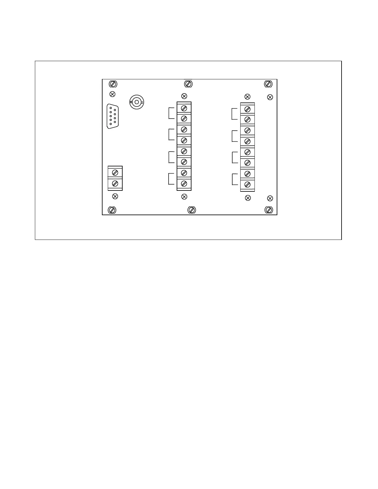
Figure 20-1. RFL 93B Relay I/O Module, rear panel
20.1 DESCRIPTION
The RFL 93B Relay I/O Module provides customer connections for the DTT and CCS trip output functions. Each
output is the normally-open contact sets of a high-speed relay that is internally energized with station battery
voltage. The RFL 93B Relay I/O Module consists of a rear panel assembly (Figure 20-1) and three subassembly
boards which are described below:
1. Power/RS-232 board. (series 100 components) Assy. No. 106388-1
2. Current Sense board. (series 200 components) Assy. No. 106388-2
3. Relay Output board. (series 1-99 components) Assy. No. 106388-3
20.2 CONTROLS AND INDICATORS
Figure 20-2 shows the location of all rear-panel connectors and terminal blocks on the RFL 93B Relay I/O mod-
ule. All of these connectors and terminal blocks are accessible with the Relay I/O Module installed in the chas-
sis. Figure 20-3 shows the location of all controls and indicators on the Power/RS-232 board. These controls
and indicators are only accessible when the Relay I/O Module is removed from the chassis, or is placed on a
card extender. The Current Sense board and the Relay Output board do not have controls and indicators and
therefore are not included under this heading.
RFL 9300 RFL Electronics Inc.
May 5, 2002 20 - 1 (973) 334-3100