DS 1
DS 2
TP 7
TP
TP 1
TP
TP 4
TP 2
TP 3
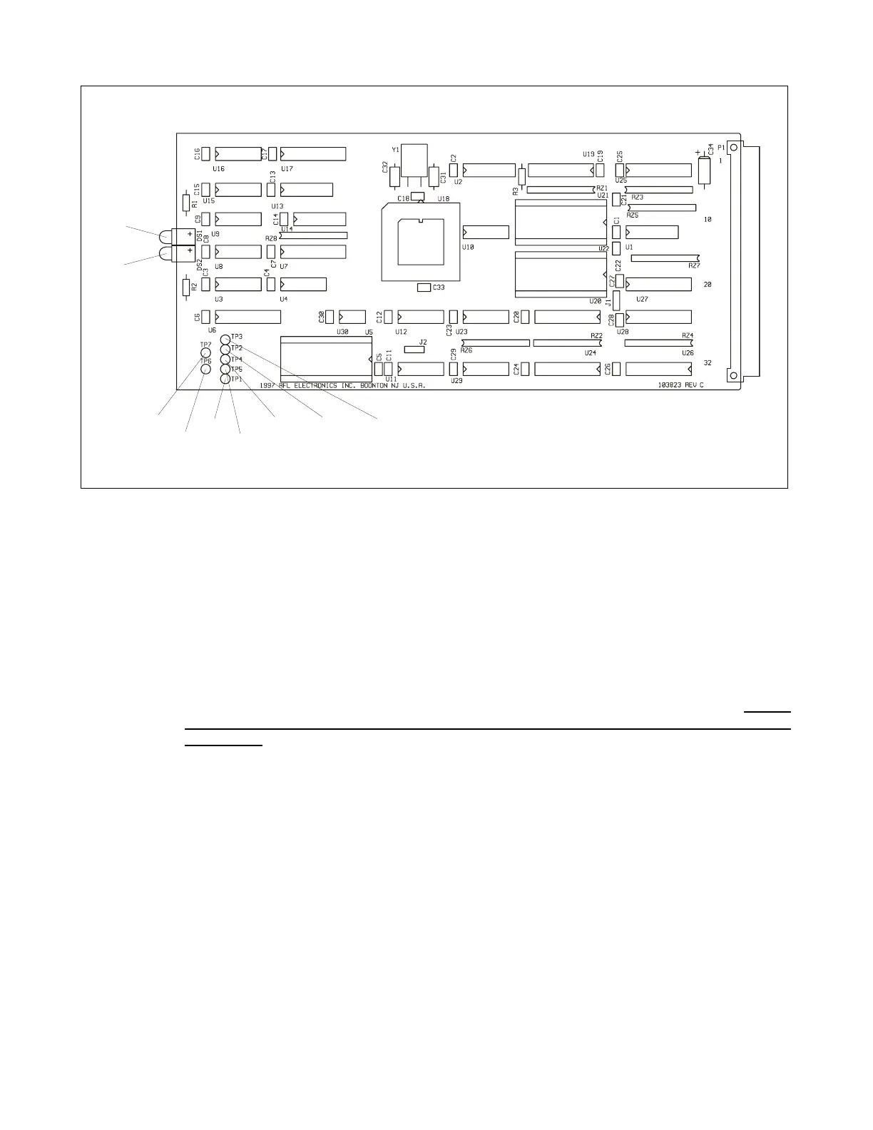
Figure 13-2. Controls and indicators, RFL 9300 communications controller module
LED INDICATORS
DS1 P-P - Front-panel indicator; lights green when a ping-pong test (round-trip delay measurement)
is in progress.
DS2 BER OK - Front-panel indicator; lights green when the bit error rate (BER) is within limits.
JUMPERS
J1 Set at the factory according to the device type installed for EPROM's U21 and U22. Do not
change the setting of this jumper, unless U21 and U22 are being replaced with another
device type.
TEST TURRETS
TP1 Measuring point for TX SYNC pulse, which must occur once per word sent.
TP2 Measuring point for TC DATA, which must be valid on positive clock edge at TP3.
TP3 Measuring point for TX CLOCK.
TP4 Measuring point for RX DATA, which must be valid on positive clock edge at TP5.
TP5 Measuring point for RX CLOCK.
TP6 Ground reference.
TP7 Measuring point for RX NOT VALID signal.
RFL 9300 RFL Electronics Inc.
February 7, 2000 13 - 2 (973) 334-3100