3.10 WEAK INFEED APPLICATIONS
"Weak infeed" is an application concern for any transmission line protection scheme. This is particularly true of pilot
wire schemes that will only trip when valid trip signals are received from both the local and remote stations. This is
referred to as a "tripping" philosophy. Since the RFL 9300 uses a tripping philosophy for enhanced security, special
provisions must be incorporated to assure proper operation in weak-feed applications.
Strong Feed
This is the normal mode of 9300 operation. In 2-terminal applications this requires 0.5 Arms and a half-cycle
pulse width of 6 ms or more at each station. The only exception is that the phase controller will transmit a
WCM when the local station breaker is open. This can result in a SFT at the receiving station if it meets the
0.5 Arms/6ms requirement and has a sensitive bias level setting. In 3-terminal applications a phase controller
will transmit a WCM if the transient current does not meet the 0.5 Arms/6 ms requirement regardless of
breaker status.
Weak Feed
This mode covers situations where one terminal does not meet the strong-feed requirements described
above. The weak-feed circuit operates when it senses a local current of 1.5 A
RMS
(or less) at the same time
it receives a remote current of 1.5 A
RMS
+ bias setting or more. These are absolute values, without re-
gard to frequency or polarity.
The difference between the RFL strong-feed and weak-feed trip algorithms is not as sharply defined as it once was
now that the WCM is used instead of the ZCM. The WCM indicates that a weak current condition exists at the send-
ing terminal. The message says nothing about breaker status. The ZCM signaled that an open breaker, based on a
52B signal, existed at the sending terminal. A CCD was transmitted, as it still is, when the control CT current
≥0.5Arms. This left a gap where no message was transmitted. Without a control signal being transmitted there was no
possibility of a SFT at the remote terminal. As noted above this has changed. The main emphasis of the weak-feed
algorithm is now to allow a faster trip at the weak-current terminal if fault detectors are active.
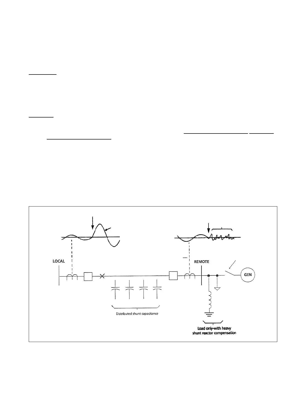
The weak-feed circuit takes care of some difficult applications, such as the one illustrated in Figure 3-15. In this appli-
cation, the shunt reactors at the remote station interact with the distributed capacitance of the protected line, produc-
ing a small current with a poor waveform.
≥ (1.5A + bias)
RMS
Small current, with
poor waveform
Generator out
of service
Fault
Figure 3-15. Weak infeed application
RFL 9300 RFL Electronics Inc.
August 25, 2000 3 - 15 (973) 334-3100