8.2.3.4 INTERNAL FAULTS
The following procedures simulate three types of internal faults: A-G, A-B, and three-phase.
8.2.3.4.1 Internal A-G Faults
This procedure demonstrates "SFT" (Strong-Feed Trip) and "UHS" (Ultra-High Speed Trip). SFT requires test
currents of at least 0.5 Arms. UHS operates whenever the test current reaches +12 Apeak for 2 ms, and the
terminal does not have a peak reading that is more negative than the peak Blocking Level (BL). The value of the
local station CT control current required to block a UHS signal received from the remote station(s), referred to
as the UHS bias value, is a function of the phase bias setting.
BL = – (11 amperes – bias amperes)peak (minimum value is 7.5A peak)
The equation applies over a limited range of phase bias settings. The range allowed is from 1-2.5 Arms. If the
value was less than 1 amp it would already have failed the range test. If the phase bias setting >2.5 Arms the
value used for the equivalent peak phase bias setting in the above equation is 3.5 A (peak). Any value greater
than this would reduce the blocking current level below 7.5 A (peak) which approaches the level of normal load
current (5 Arms max). It is not desirable to have normal load current levels block UHS since this would essen-
tially disable the function.
Example: For a bias setting of 3 amperes rms (4.2A peak):
BL = – (11 amperes – 4.2 amperes) = – 6.8A peak
BL = – 7.5 amperes peak (minimum value)
UHS is usually about 5 ms faster than SFT.
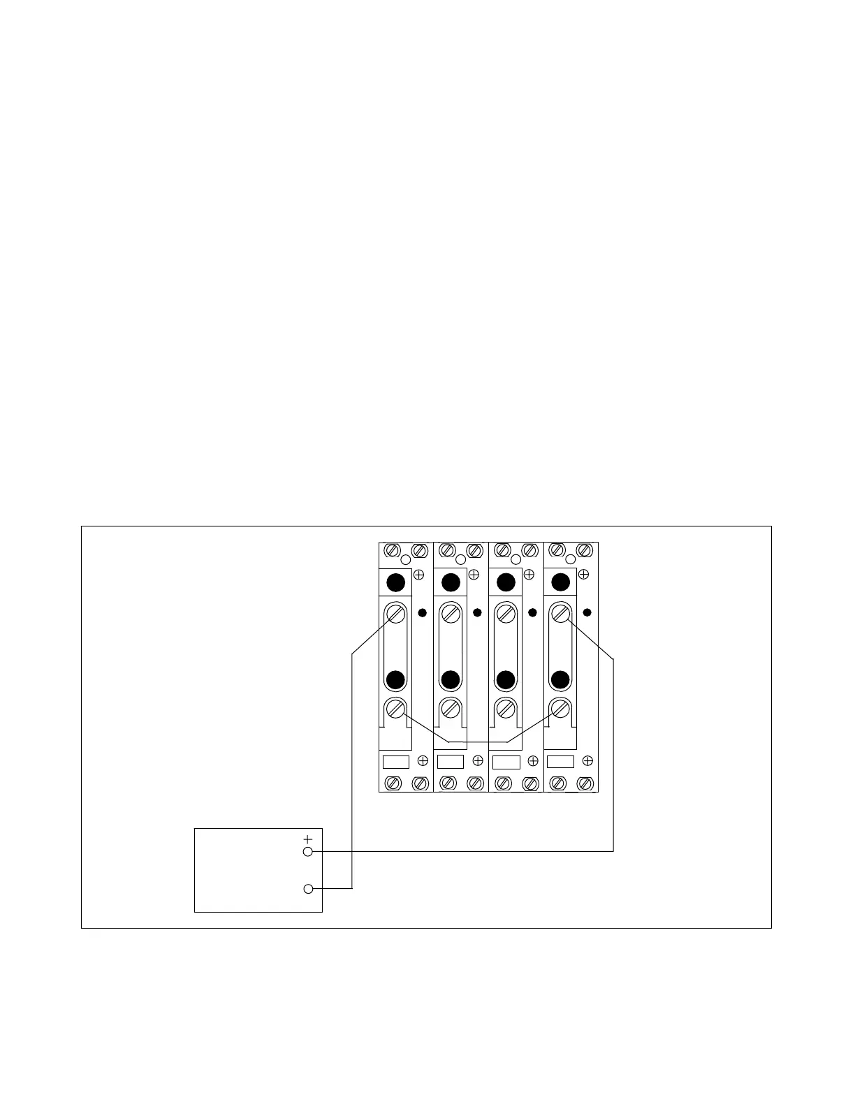
1. Connect the equipment as shown in Figure 8-2.
This creates an "internal" current line-up for Phase A and ground.
AC
CURRENT
SOURCE
TB4
TB5
A
C
T
A
C
T
TB6
TB7
A
C
T
A
C
T
1
1 1 1
2
2
2
2
3I
0
I
C
I
B
I
A
Figure 8-2. Test connections simulating an internal A-G fault
RFL 9300 RFL Electronics Inc.
October 20, 2004 8 - 12 (973) 334-3100