2.7.6 OPEN CONDUCTOR ALGORITHM
The open conductor algorithm is the only non-backup mode function that does not rely on the communications
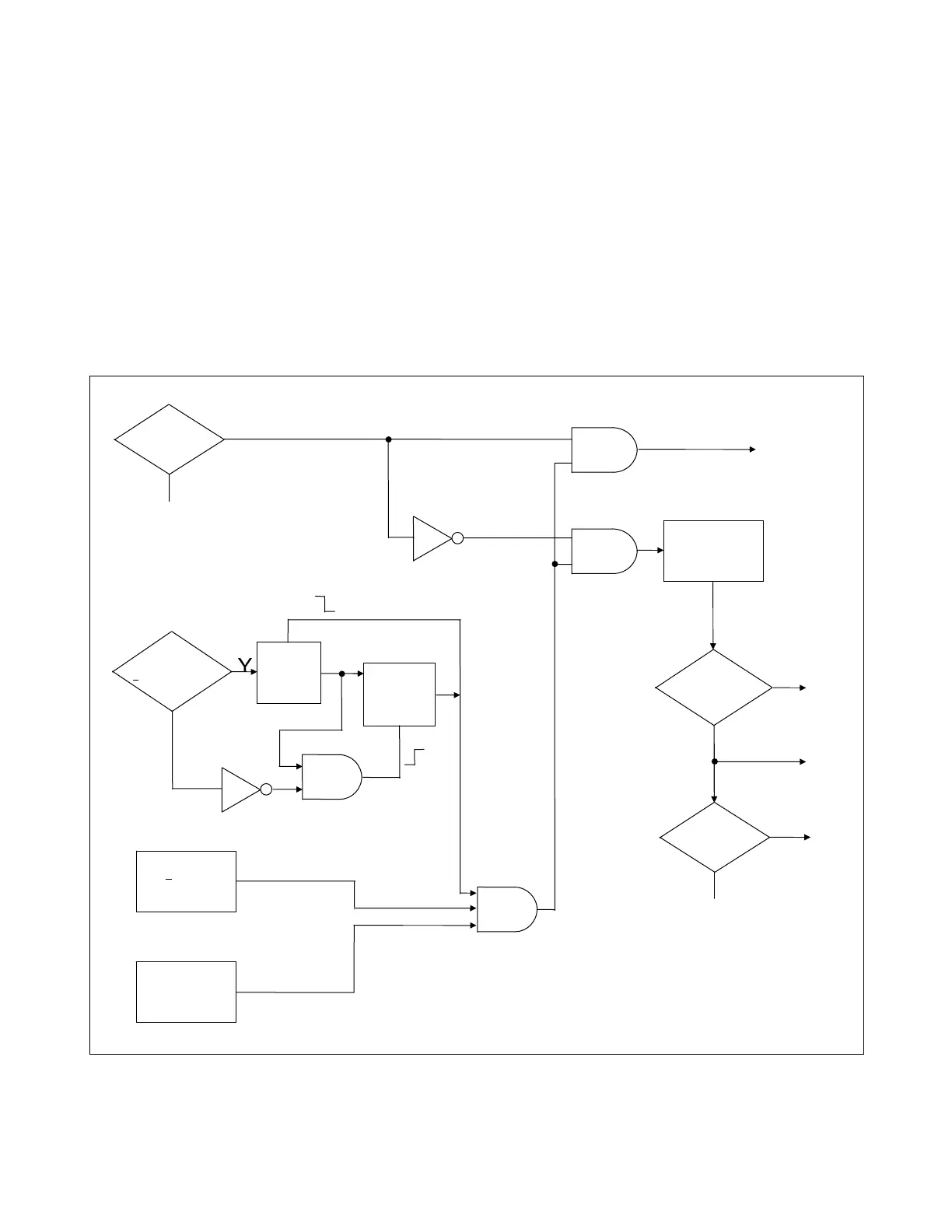
link. (See Figure 2-8.) This function is enabled when the Phase A, Phase B and Phase C controllers all have a
load current ≥ 1.5 Arms. From this point on the function looks for a loss of load current on one or more phases
while at least one of the remaining phases carries at least 3A of load current. The open conductor requires fault
detector supervision. The phase detector executing the algorithm must have a composite phase fault detector. A
500-ms Zone 2 timer starts when the open conductor condition is detected. This timer gives the Zone 2 protec-
tion relays time to clear the fault in the event that the fault exists beyond the remote breaker. If the open conduc-
tor condition is still present when this timer expires, the open conductor trip signal or alarm will be issued, de-
pending on how the RFL 9300 is programmed.
Note that when the RFL 9300 is programmed for trip on open conductor, this function issues a trip signal, not a
trip enable signal. This is because the fault detectors probably will no longer be active when the Zone 2 timer
expires.
AND
AND
AND
AND
TRUE
CT CURRENT
>
1.5A ON EACH
PHASE ?
CLEAR
LATCH
ENABLE
START
32 MS
TIMER
FAULT CURRENT
>
3A ON
ONE OR MORE
PHASES
FAULT CURRENT
<0.5A ON
ONE OR MORE
PHASES
BACKUP
ENABLED
?
YES
NO
NO
500 MS
ZONE 2
TIME DELAY
LOSS-OF-LOAD
CONDITION
TRIP AND
ISSUE CCT-U
TO REMOTE
TERMINAL
OPEN
CONDUCTOR
CONDITION
OPEN
CONDUCTOR
PROGRAMMING
TRIP
ENABLED
?
ACTIVE
ALARM
ACTIVE
ALARM
NO
YES
TRIP AND
ISSUE CCT-U
TO REMOTE
TERMINAL
ALARM
ONLY
TRIP AND
ALARM
Figure 2-8. Logic diagram for open conductor and loss of load algorithm
RFL 9300 RFL Electronics Inc.
October 29, 2001 2 - 21 (973) 334-3100