SECTION 16: DIRECT DIGITAL INTERFACE I/O MODULE
D D
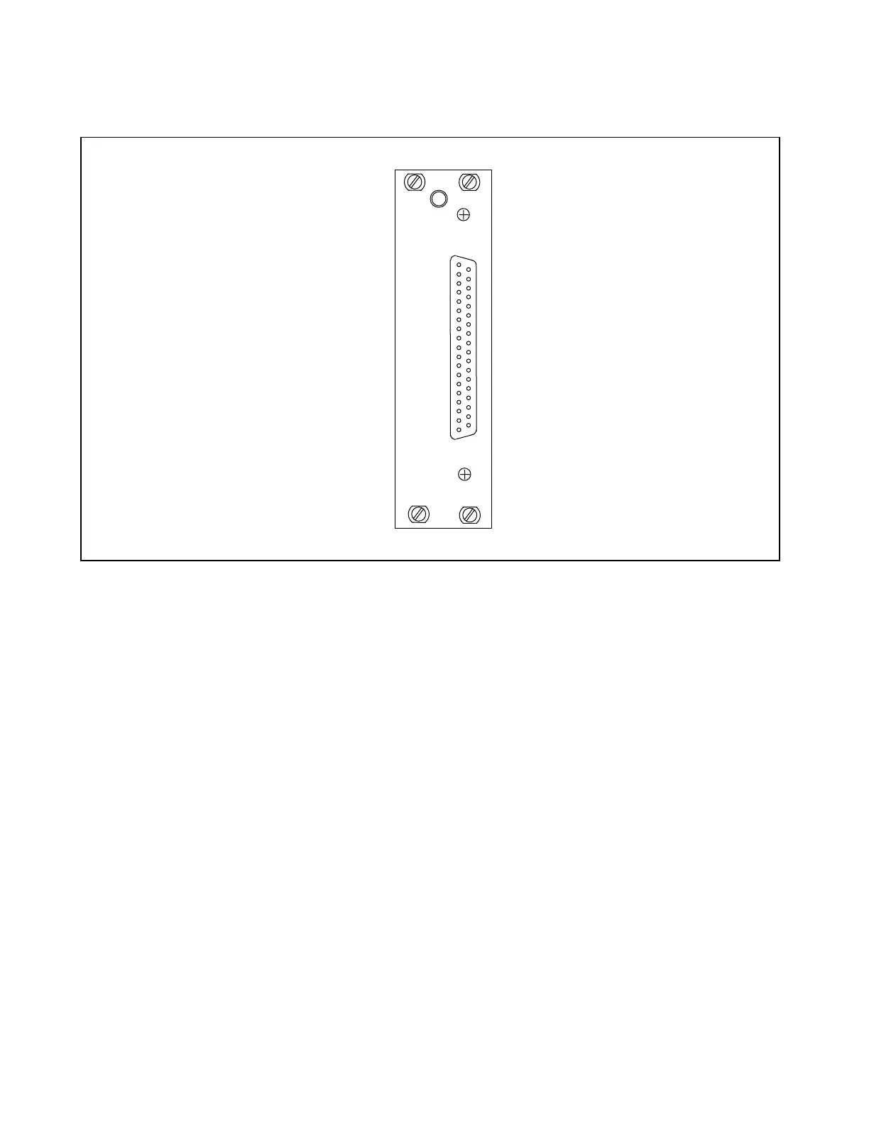
Figure 16-1. RFL 93 DD I/O Direct Digital Interface I/O Module
16.1 DESCRIPTION
The RFL 93 DD I/O Direct Digital Interface I/O Module (Fig. 16-1) allows digital communications equipment
(DCE) to be connected directly to the RFL 9300. It serves as an interface between the RFL 9300's motherboard
and a rear-panel connector that accepts RS-422 signals. The RFL 93 DD I/O acts only as a buffer, unless the
system is configured for hot standby. Multiplex circuits on the RFL 93 DD I/O provide the alternate data paths
used during hot standby.
16.2 CONTROLS AND INDICATORS
The RFL 93 DD I/O's circuit board contains two programmable jumpers that prepare it for use, and a rear-panel
37-pin D-subminiature connector. Figure 16-2 shows the jumper locations, and their functions are described
below. The jumpers can only be accessed when the RFL 93 DD I/O is out of the chassis or is on a card ex-
tender.
RFL 9300 RFL Electronics Inc.
May 1, 1998 16 - 1 (973) 334-3100