25.2 FRONT PANEL RS-232 INTERFACE MODULE
The RS-232 interface module provides the RFL 9300 with a front panel RS-232 port. There is also an RS-232
port on the rear panel of the 9300 chassis which is located on the Relay I/O module. This can be seen in Figure
20-1. The rear panel RS-232 port is normally active. When the front port is activated, the rear port is automati-
cally deactivated. The front port is activated by enabling the DTR line on pin 4 of the standard DB9 female con-
nector. This will normally happen with any communication software running on a laptop. A straight through male
to female cable is required for most computers.
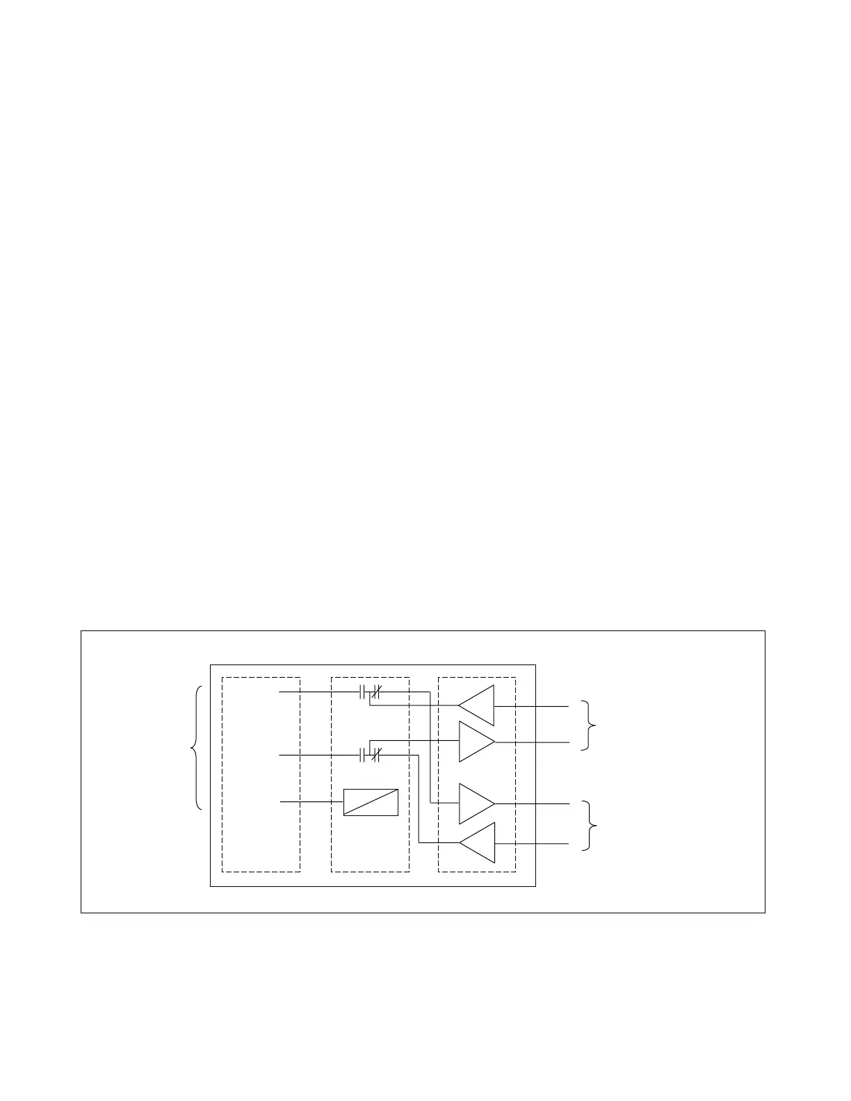
25.2.1 THEORY OF OPERATION
For the following discussion, refer to Figures 25-2 and 25-6
The RS232 board (106755) mounts to the front panel of the 9300 and connects via a cable to the Display Con-
troller. It operates in two modes, Pass Through or Insert.
In Pass Through mode the TTL level Transmit and Receive lines coming from the 80C196 on the display con-
troller are converted to RS-232 levels by U1, run through relay K1 and are converted back to TTL levels by U1.
These signals are then connected back through the Display Controller to the Relay I/O, where they are routed to
the rear RS-232 port. Pass Through mode is invoked whenever nothing is connected to the front RS-232 con-
nector.
In Insert Mode the Transmit and Receive lines from the front RS-232 port are routed via the relay K1 to U1
where they are converted to TTL levels and connected to the Display Controller processor. In this mode the sig-
nals from the Relay I/O are disconnected from the rest of the system. Insert Mode is invoked when K1 is ener-
gized.
K1 is energized when the DTR line (pin 4 on J1) is active. This normally happens when a PC terminal emulation
program takes control of the PC port. A straight through 9-pin cable is all that is needed to drive this signal ac-
tive. This signal causes Q2 and Q1 to conduct and turn on the relay K1.
If no source for DTR is present, the relay can be forced active by putting jumper JP1 in the B position and using
a special cable with pin 1 grounded. This will turn on Q1 and energize the relay. Jumper JP1 should be placed
in the A position for normal system operation.
K1 U1
TX DATA
RX DATA
DTR
J1 DB9
To serial
port of
ersonal
To processor on
Display Controller
To rear RS-232 port
Via Display Controller
106755 RS-232 Front Board
Figure 25-2. Block diagram of RS-232 front board
RFL 9300 RFL Electronics Inc.
May 5, 2002 25 - 2 (973) 334-3100