7.4.3 EXTERNAL A-G FAULTS
This procedure will prove out the ac current measurement function, the fault detector response, and stability
during external faults.
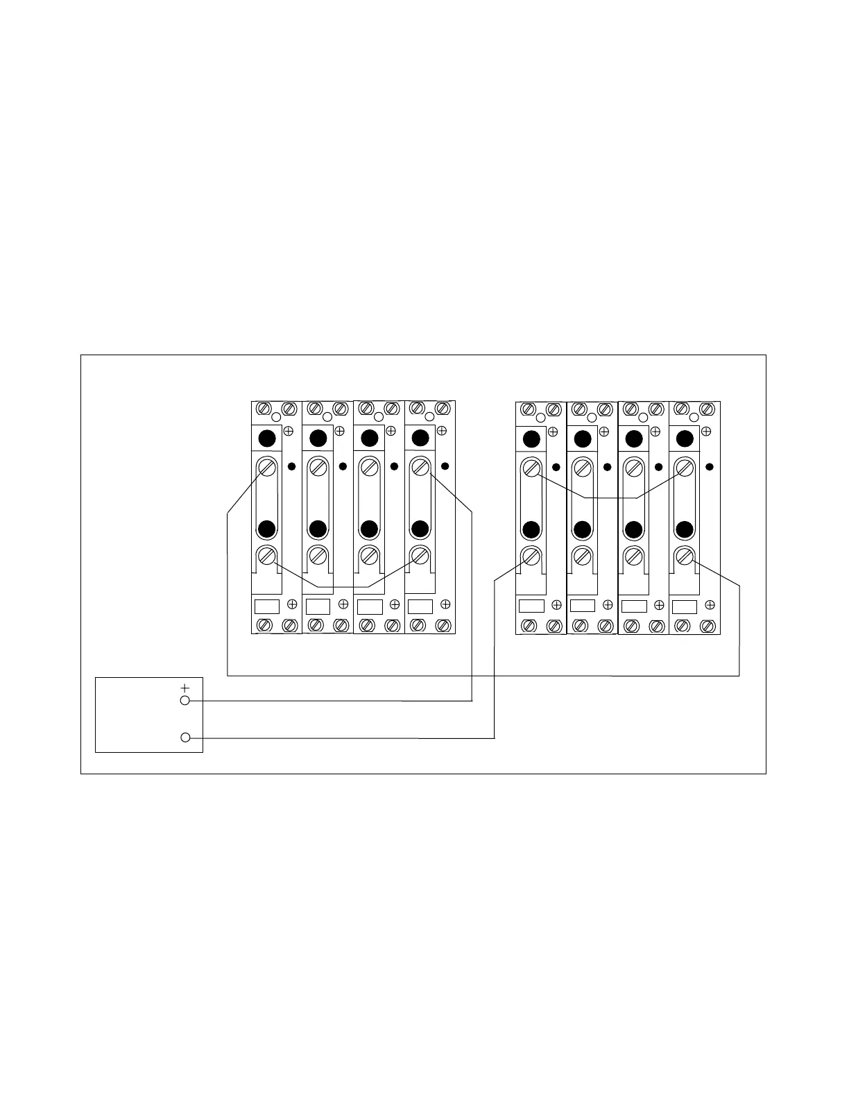
1. Connect a single-phase ac current source to both RFL 9300s. (See Figure 7-2).
This simulates an external A-G fault. At the left RFL 9300, test current is injected into
the Phase A polarity terminal and the 3I
0
non-polarity terminal. At the right RFL 9300,
the polarities are opposite.
The system external connection diagrams in Section 5 of this manual show the 3I
0
cur-
rent connected to the non-polarity terminal of the ground ACT (rear-panel terminal TB4-
2). This effectively inverts the polarity of the residual current relative to the phase cur-
rents. This technique provides tripping on each half-cycle for ground faults. By invert-
ing the polarity of 3I
0
relative to I
A
, the test circuit of Figure 7-2 follows this technique.
AC
CURRENT
SOURCE
TB4
TB5
A
C
T
A
C
T
TB6 TB7
A
C
T
A
C
T
3I
0
I
C
I
B
I
A
1 1 1 1
2 2 2 2
TB4
TB5
A
C
T
A
C
T
TB6
TB7
A
C
T
A
C
T
3I
0
I
C
I
B
I
A
1 1 1 1
2 2 2 2
LEFT TERMINAL RIGHT TERMINAL
Figure 7-2. Test connections simulating an external A-G fault
2. Vary the magnitude of the ac test current. Place either RFL 9300 in the READ display mode, and ver-
ify that the Phase A and 3I
0
currents are the same value as the test current.
The currents can be checked by viewing the following parameters:
Local Phase A current Parameter #5 (LOC IA)
Local 3I
0
current Parameter #8 (LOC 3I0)
Remote Phase A current Parameter #9 (REM1 IA)
Remote 3I
0
current Parameter #12 (REM1 3I0)
RFL 9300 RFL Electronics Inc.
October 20, 2004 7 - 8 (973) 334-3100