DS 1
DS 2
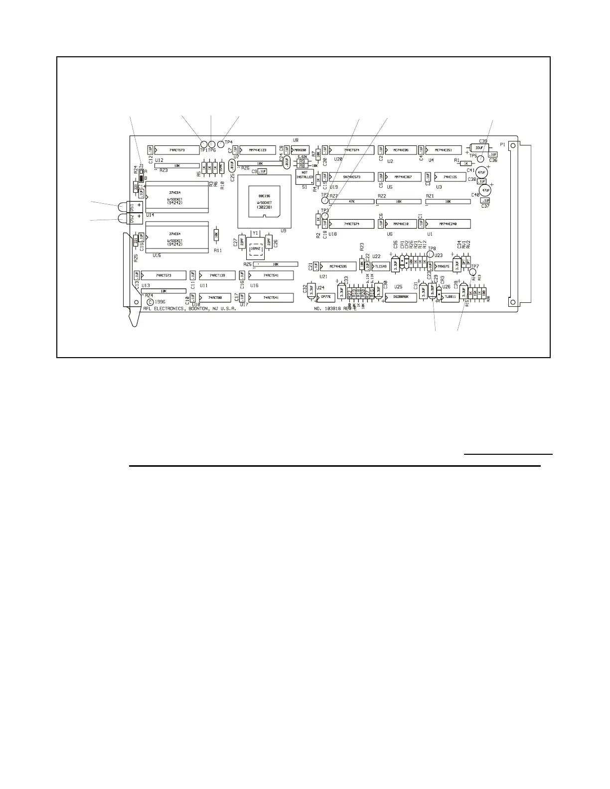
J1
TP 1
TP 4
TP 2 TP 3
TP 5
TP 7
TP
Figure 12-2. Controls and indicators, RFL 9300 phase controller modules
JUMPERS
J1 Set at the factory according to the type of device installed for U14 and U15. Position A is used
for 27C256 devices, and Position B is used for 27C64 or 27C128 devices. Do not change the
setting of this jumper, unless U14 and U15 are being replaced with another device type.
TEST TURRETS
TP1 Positive watchdog timer pulse signal. This narrow-pulse signal should appear at 500-ms inter-
vals for 60-Hz systems, and 600-ms intervals for 50-Hz systems.
TP2 Monitoring point is a 1μs positive clock pulse starting 497μs after the rising edge of the system
clock signal applied to U9-24 (HSI.0). For 50-Hz systems, this pulse will start 597μs after the
leading edge of the system clock signal.
TP3 Monitoring point for the system clock signal supplied by the RFL 93B SV Supervisor Controller.
The clock frequency is 2 kHz for 60-Hz systems, and 1.667 kHz for 50-Hz systems. When the
relay is configured for 3-terminal operation, the system clock is phase locked to the line current
at a frequency equal to 33 times the line frequency in Hz.
TP4 Monitoring point for the READY/BUSWIDTH signal. This signal should go low whenever a
memory-mapped I/O access is executed. All memory-mapped I/O resides at addresses of
8000H or higher, or when U12-19 is high. Whenever TP4 is low, one wait state is added to the
external bus cycles, and the microcontroller's bus width dynamically switches from 16 bits to 8
bits.
RFL 9300 RFL Electronics Inc.
March 26, 1999 12 - 2 (973) 334-3100