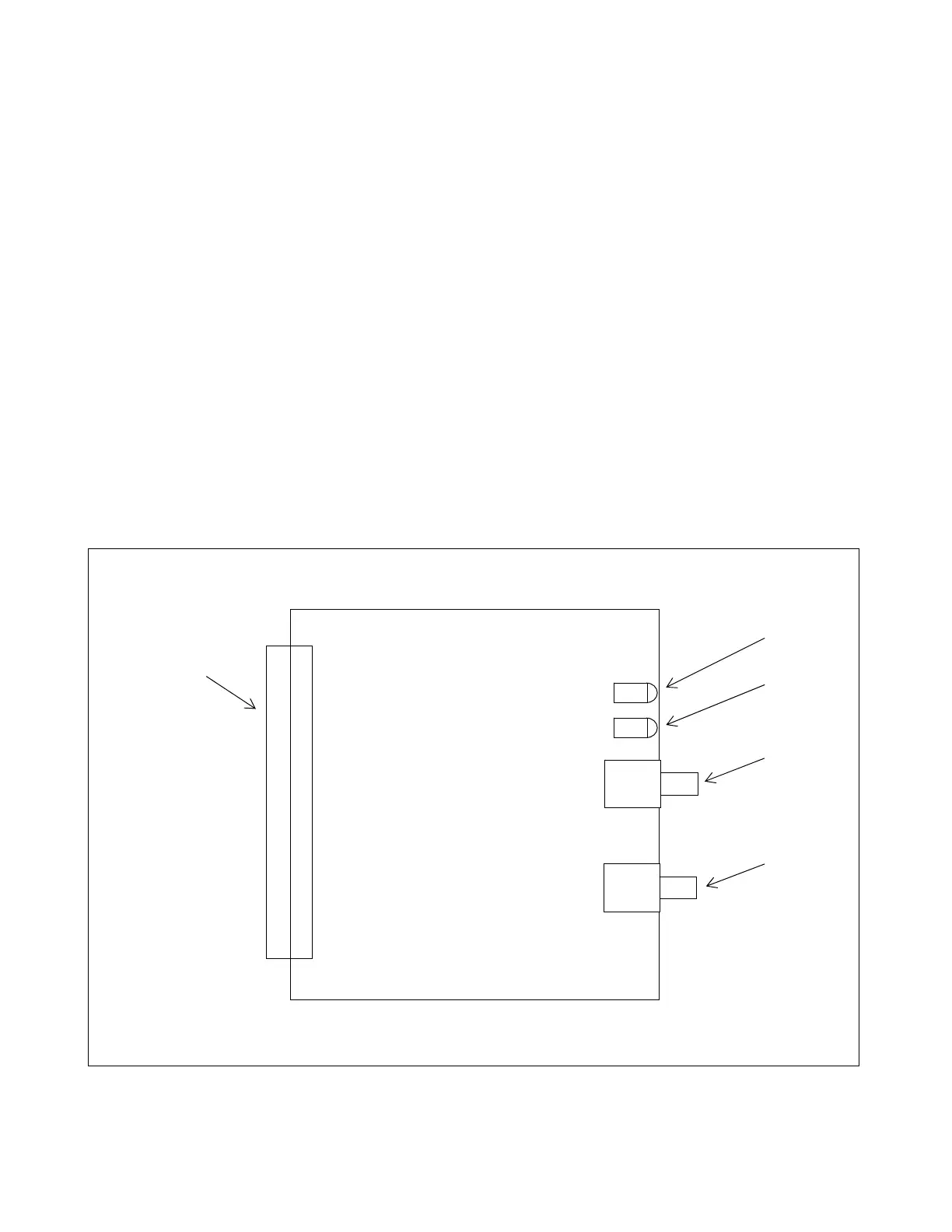
22.2.3 CONTROLS AND INDICATORS
Figure 22-2 shows the location of all controls and indicators on the RFL 93 SH FIBER module. These controls
and indicators are described below.
Controls
DS9 Fiber optic emitter
U7 Fiber optic detector
J1 Motherboard connector
Indicators
D1 Data LED (Green): Loss of signal when not illuminated.
Active when fiber data is valid with no bit errors.
Extinguished indicates loss of signal.
Pulsing indicates bit errors.
D2 Yellow Alarm LED (Amber): Yellow alarm when illuminated.
Indicates that the remote fiber receiver has failed and
the remote transmitter is sending yellow code detected
by the local fiber receive channel.
D1
D2
U7
DS9
J1
Figure 22-2. Controls and indicators, RFL 93 SHFI short haul fiber interface module
RFL 9300 RFL Electronics Inc.
October 20, 2004 22 - 4 (973) 334-3100