In 3-terminal systems the adjusted received time-tags are used to select a locally stored half-cycle nested by
both CCD, WCM or a combination of these control signals received from the remote stations. Once this deter-
mination is made the remote signals must be combined to form a composite signal that will be compared with
the selected or “nested” local half-cycle integral when executing the SFT algorithm.
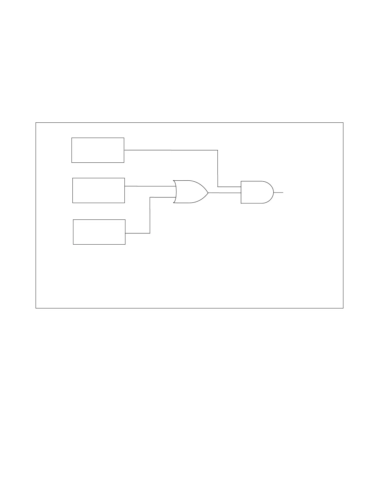
The open conductor algorithm depends only on current values read at the local station. When a trip condition
exists, the algorithms produce a trip enable signal; this is a necessary but not sufficient condition to cause a trip
signal to be issued. Besides the trip enable signal, at least two fault detectors must be active somewhere in the
system. (See Figure 2-2.) One of the active detectors must be the fault detector for the phase in question. A
RFL 93B PC will only issue a trip signal without having an active fault detector if it receives a trip signal (CCT-U)
from the remote RFL 9300.
FD OF THE
LOCAL PHASE
IN QUESTION
1
FD OF ANY OTHER
LOCAL PHASE OR
GROUND
2
ACTIVE FD
AT REMOTE
STATION
2
“COMPOSITE FD”
OF THE LOCAL
PHASE/GROUND
IN QUESTION
OR
AND
1. In a two terminal system, if the 3Io controller has an active fault detector it will compute a composite
FD when the remote breaker is open. For this special case additional fault detectors are not required.
2. In three terminal systems this does not include the overcurrent fault detector for the phase A, phase
B or phase C controllers. The overcurrent fault detector of the 3Io controller is “global” for only 125
ms after it becomes active.
Figure 2-2. Logic diagram, composite fault detector
2.7.2 STRONG-FEED TRIP (SFT) ALGORITHM
The SFT algorithm detects strong internal faults. (See Figure 2-3.) The RFL 9300 enters a special LCCT (Local
Current Comparison Trip) alarm mode if the SFT algorithm produces a trip enabled signal under the following
conditions:
1. The necessary fault detectors were not activated to cause a trip signal to be issued.
2. This condition persists for 10 consecutive nested half-cycles of CT current.
This mode will persist for 5 seconds. During this time, the affected phase controller is disabled. The other phase
controllers remain active to provide protection for all fault types, except open conductor. After the 5-second in-
terval expires, the phase controller will re-initialize and attempt to come back-on line. As long as this condition
exists, the LCCT alarm will be active. This alarm mode protects the RFL 9300 against A/D converter failures.
RFL 9300 RFL Electronics Inc.
October 29, 2001 2 - 14 (973) 334-3100