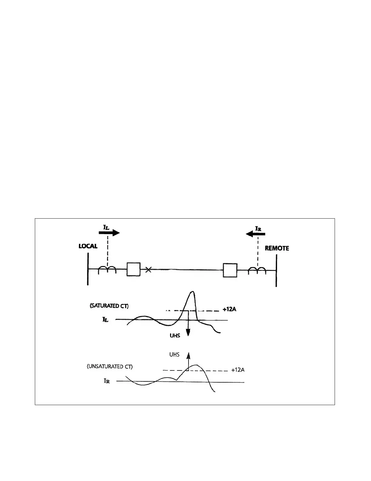
3.9 SATURATED MAIN CURRENT TRANSFORMERS
The main current transformers are particularly subject to saturation on close-in internal faults. A general rule of
thumb is that the CTs used in relay applications will reproduce the primary current waveform with acceptable
accuracy for at least a half-cycle or more. The UHS algorithm is designed to execute during this interval. This
provides high-speed clearing for this condition.
3.9.1 INTERNAL FAULT CALCULATION
Two separate calculations should be made to select the proper CT's: one for "SLG" (single-line-to-ground)
faults, and one for three-phase faults. Use the following formula for SLG faults:
V
KPS
= I
SLG
x R
2W
x TF
G
where
V
KPS
= Kneepoint voltage of the CT's B-H curve for worst-case SLG fault.
I
SLG
= Maximum expected SLG fault current (symmetrical, in secondary amperes rms).
R
2W
= "Two-way" secondary cable resistance, in ohms.
TF
G
= "Transient factor" for ground faults. This is equal to (1 + X
L
/R) where (L/R) is the primary system
time constant.
Figure 3-13. Saturated main current transformers during close-in internal fault
RFL 9300 RFL Electronics Inc.
August 25, 2000 3 - 11 (973) 334-3100