18.5 THEORY OF OPERATION
Single width fiber optic I/O modules contain both emitter and detector circuitry making them suitable for both
transmission and reception of light signals over an optic fiber. Although all I/O modules perform the same func-
tion, each operates in a slightly different manner, so theories of operation are provided for each fiber optic I/O
module which are described below.
18.5.1 RFL 93 FT/FR-8M
Overview
The RFL 93 FT/FR-8M single width fiber optic I/O module contains both LED emitter and photodiode detector
circuitry. The transmit section consists of the LED, LED current driver, and alarm circuits to detect misoperation
due to component failures. The receive section consists of the APD (Avalanch Photo Diode), high voltage tank
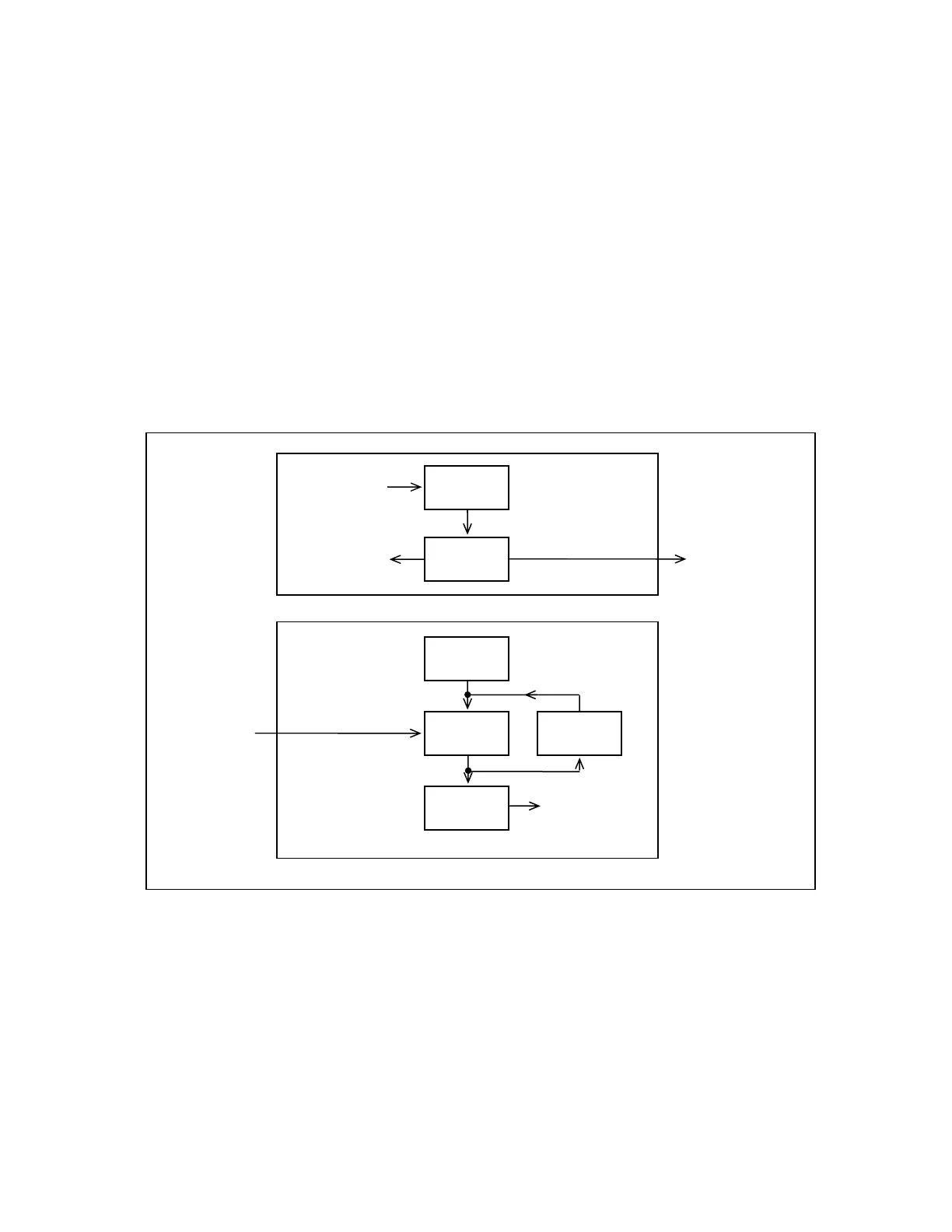
circuit, shunt current regulator, several stages of amplification and a schmitt trigger output stage. A block dia-
gram is shown in Figure 18-5, and a schematic diagram is shown in Figure 18-9.
DRIVER
EMITTER
HIGH-VOLTAGE
SUPPLY
PHOTODIODE
OUTPUT
AMPLIFIER
SHUNT
REGULATOR
LIGHT INPUT
FROM FIBER
OPTIC CABLE
LIGHT OUTPUT
TO FIBER
OPTIC CABLE
OUTPUT TO
FIBER OPTIC
TRANSCEIVER
MODULE
INPUT FROM
FIBER OPTIC
TRANSCEIVER
MODULE
ALARM FEEDBACK
TO FIBER OPTIC
TRANSCEIVER
MODULE
Figure 18-5. Block diagram, RFL 93 FT/FR I/O-8M 850 nm Multimode Fiber Optic I/O Module
Transmit Section
The fiber optic LED U1 is driven from a current source generated by Q1 and Q2. The unmodulated bias current
through the LED is controlled by R2 and R20, which sets the bias voltage for emitter followers Q1 and Q2. The
voltage across R9 produces a bias current which is essentially the same as the LED current. This causes the
LED to emit, without modulation, a constant light output at approximately the average output power.
RFL 9300 RFL Electronics Inc.
January 19, 2005 18 - 7 (973) 334-3100