2.8 BACKUP MODE OPERATION
Except for the open conductor algorithm, the RFL 9300 cannot execute any of its charge comparison protection
algorithms if the communications channel to the remote station is disrupted. If a communications failure occurs,
some degree of protection is still provided. Whenever the RFL 93B CC Communications Controller detects a
communications failure, it signals the phase controllers to enter the backup mode. If the operator has enabled
backup (through the keypad), the local RFL 9300 will enter backup mode, disable permissive trip signals, and
execute the backup protection algorithms. Some form of fault detector supervision is still required to cause a
backup trip signal to be issued. As long as communications still exist between the phase controllers and the su-
pervisor controller, one additional local RFL 9300 fault detector (besides the phase controllers' own fault detec-
tor) must be active for a backup trip signal to be issued.
If the operator has enabled the backup mode, the phase controllers can enter backup mode without being com-
manded to do so by the RFL 93B SV. This will happen if all four phase controllers at the local terminal have an
active alarm. This condition can occur if there is a problem with the parallel bus linking the RFL 93B SV with the
phase controllers. It also can occur if the RFL 93B SV is malfunctioning. Then only the phase controllers‘ local
fault detector is required to supervise a backup trip signal.
While operating in backup mode, each phase controller will continue to execute all protection algorithms. It will
still attempt to transmit all signals, including trip signals, to the remote terminals on the chance that they may get
through. The only difference is that now, backup trip signals are enabled while permissive trip signals are dis-
abled.
The protection algorithms listed below are active when a phase controller operates in backup mode.
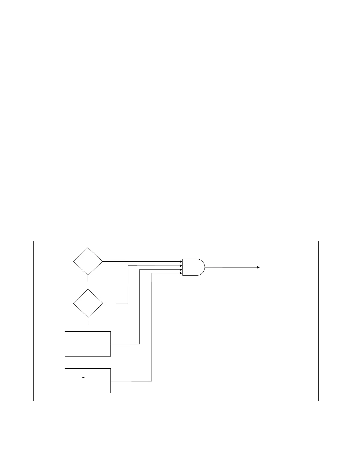
2.8.1 SWITCH-INTO-FAULT WITHOUT COMMUNICATIONS (SIF W/O C)
The (SIF W/O C) algorithm looks for individual phase currents greater than 10 Arms lasting at least 16 ms. It
enables a backup trip signal if this condition is detected. This function will detect the presence of an internal fault
when the local breaker is closed into the fault with the remote breaker still open. The function will remain active
for 50 ms after breaker closing. (See Figure 2-10.)
AND
SWITCH-INTO FAULT
CONDITION
TRIP
AND ISSUE CCT-U
TO REMOTE TERMINAL
NO
YES
NO
YES
> 10A
ON ANY
PHASE OR GROUND
50-ms TIME
WINDOW, SET BY
BREAKER CLOSING
LOSS OF
CHANNEL
?
BACKUP
ENABLED
?
Figure 2-10. Logic diagram, switch-into-fault without communications
RFL 9300 RFL Electronics Inc.
October 29, 2001 2 - 25 (973) 334-3100