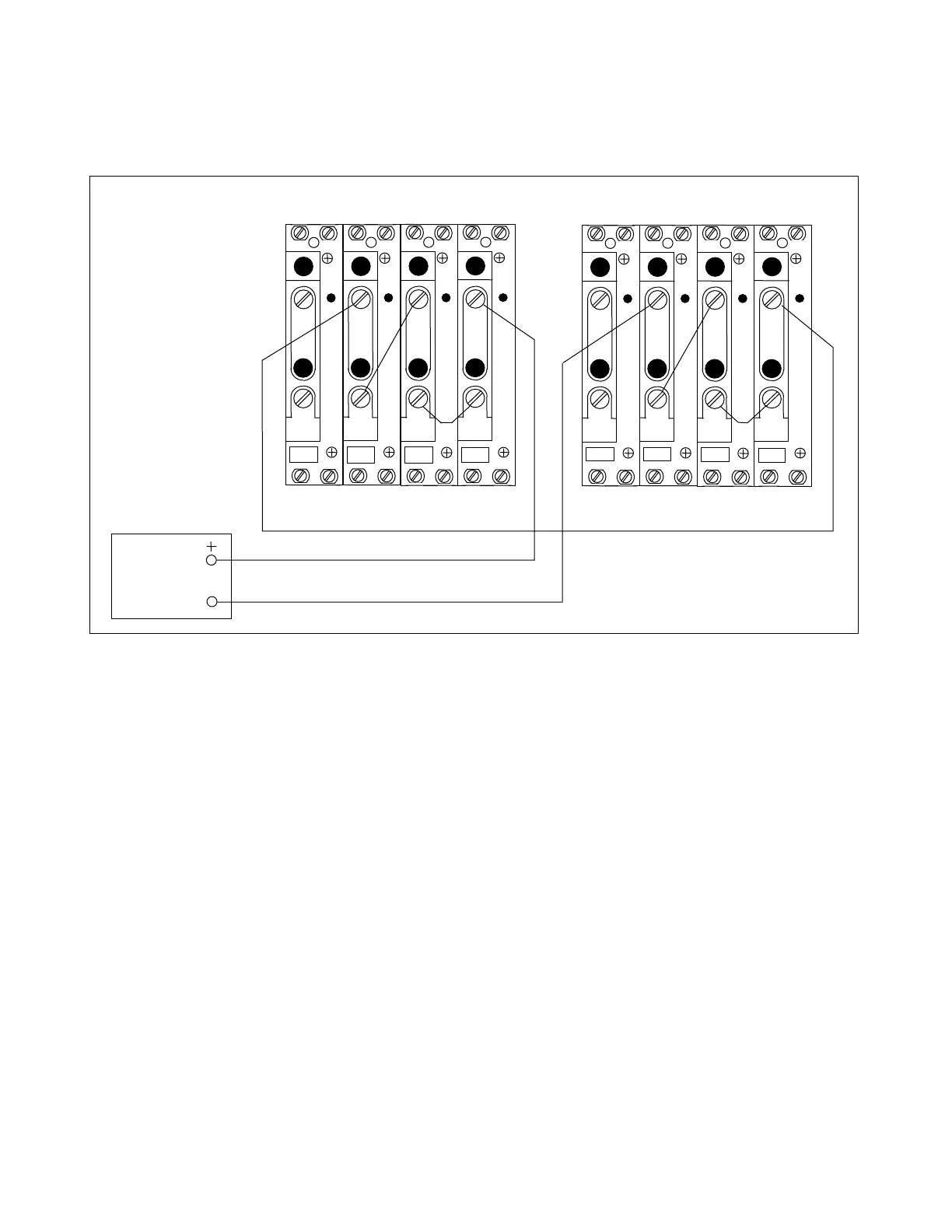
7.4.7 INTERNAL THREE-PHASE FAULTS
1. Connect the test circuit shown in Figure 7-9.
AC
CURRENT
SOURCE
TB4
TB5
A
C
T
A
C
T
TB6
TB7
A
C
T
A
C
T
3I
0
I
C
I
B
I
A
1 1 1 1
2 2 2 2
TB4
TB5
A
C
T
A
C
T
TB6
TB7
A
C
T
A
C
T
3I
0
I
C
I
B
I
A
1 1 1 1
2 2 2 2
LEFT TERMINAL RIGHT TERMINAL
Figure 7-9. Test connections simulating an internal three-phase fault
2. Apply test currents of various levels.
Results should be similar to the results obtained for the A-B fault simulation, except all
three phase targets (A, B and C) should now operate. The reclose block output (termi-
nals TB9-1 and TB9-2) also should operate.
7.4.8 OTHER INTERNAL FAULT TYPES (optional)
The other phase-to-ground (B-G and C-G) and phase-to-phase (B-C and C-A) internal faults may be simulated
by modifying the test circuit connections shown in Figures 7-7 and 7-8 to energize the other phases.
RFL 9300 RFL Electronics Inc.
October 20, 2004 7 - 16 (973) 334-3100