7.3
Date Code 20171006 Instruction Manual SEL-400 Series Relays
Metering
Instantaneous Metering
Some products include Relay Word bits to indicate the leading or lagging power
factor (see Section 11: Relay Word Bits in the product-specific instruction man-
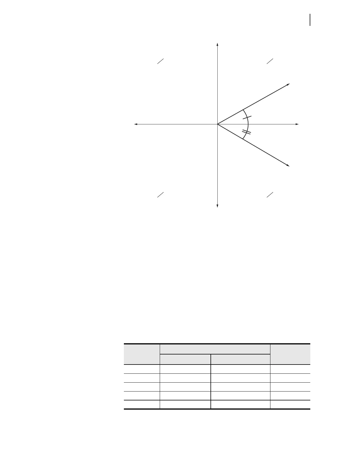
ual). In the case of a unity power factor or loss of phase or potential condition, the
resulting power factor angle would be on this axis of the complex power (P/Q)
plane shown in Figure 7.1. This would cause the power factor Relay Word bits to
rapidly change state (chatter). Be aware of expected system conditions when
monitoring the power factor Relay Word bits. It is not recommended to use chat-
tering Relay Word bits in the SER or anything that will trigger an event.
High-Accuracy Instantaneous Metering
The relay is a high-accuracy metering instrument. Table 7.2 and Table 7.3 show
the metering accuracy for the relay instantaneous metering quantities at nominal
power system frequency and at 20°C. Use a method similar to that in
Example 7.1 to compute exact error coefficients.
Figure 7.1 Complex Power (P/Q) Plane
Q
P
+P
+Q
C
o
mpl
e
x
P
o
wer
S
1
C
om
p
l
e
x
P
o
we
r
S
2
pf = Lead
pf = Lag
—P
+Q
+P
—Q
—P
—Q
Export power and
export reactive power
(inductive load)
Export power and
import reactive power
(capacitive load)
Table 7.2 Instantaneous Metering Accuracy—Voltages, Currents, and Frequency
Quantity
Magnitude Accuracy
Phase Accuracy
Range Specification
V, V 33.5 – 200 V
L–N
± 0.1% +0.05°
3V0, V1, 3V2 33.5 – 200 V
L–N
± 0.15% +0.10°
I (0.5 – 3)• I
NOM
±0.2% ± (0.8 mA) • I
NOM
+0.20°
3I0, I1, 3I2 (0.5 – 3)• I
NOM
± 0.3% ± (1.0 mA) • I
NOM
+0.30°
40–65 Hz ±0.01 Hz