8.5
Date Code 20171006 Instruction Manual SEL-400 Series Relays
Monitoring
Circuit Breaker Monitor
Circuit Breaker Contact Wear Curve Details
Circuit breaker maintenance information from the two end values of Table 8.2 or
Figure 8.2 determine set point (B1KASP1, B1COSP1) and set point (B1KASP3,
B1COSP3) for the contact wear curve of Figure 8.3. Set point (B1KASP2,
B1COSP2) is the middle maintenance point in these data. There are two philoso-
phies for selecting the middle set point. One method places the middle set point
to provide the best “curve-fit” for your plot of the manufacturer’s circuit breaker
maintenance data (shown in Figure 8.2). Another philosophy is to set the middle
point based on actual experience or fault studies of the typical system faults.
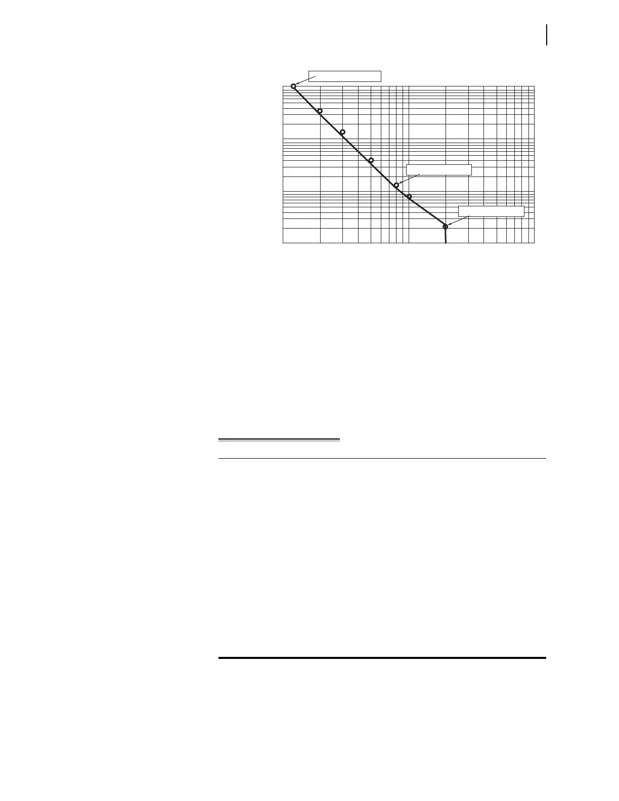
There are two other notable portions of the circuit breaker contact wear curve in
Figure 8.3. The curve is horizontal below the left set point (B1KASP1, B1CO-
SP1). This is the close/open operation limit regardless of interrupted current
value (for the Example 8.1 circuit breaker, this is at B1COSP1 := 10000). Some
manufacturers call this point the mechanical circuit breaker service life.
Figure 8.3 Circuit Breaker Contact Wear Curve With Relay Settings
B1COSP2
1 10 100
kA Interrupted per Operation (kA)
Number of Close/Open Operations
10000
1000
100
10
B1COSP3
B1KASP1 B1KASP2 B1KASP3
(B1KASP1, B1COSP1)
(B1KASP2, B1COSP2)
(B1KASP3, B1COSP3)
B1COSP1
Example 8.1 Creating the Circuit Breaker Contact Wear Curve
Acquire the manufacturer’s maintenance information (this example uses the
data of Table 8.2 for Circuit Breaker 1). If you receive the data in tabular
form, plot the manufacturer’s maintenance information on log/log paper in a
manner similar to Figure 8.2.
Choose the left and right set points from the extremes of the curve you just
plotted. Select the left set point on the contact wear curve corresponding to
(B1KASP1, B1COSP1) by setting B1KASP1 := 1.2 and B1COSP1 := 10000.
Plot the right set point (B1KASP3, B1COSP3) by setting B1KASP3 := 20.0
and B1COSP3 := 12.
Choose the midpoint of the contact wear curve based on your experience and
system fault studies. The majority of operations for a typical circuit breaker
are to interrupt single-line-to-ground faults. Therefore, plot the midpoint
(B1KASP2, B1COSP2) by setting B1KASP2 at or slightly greater than the
expected single-line-to-ground fault current: B1KASP2 := 8.0 and
B1COSP2 := 150.